Rotor for a turbomachine

a turbomachine and rotor technology, which is applied in the direction of machines/engines, mechanical apparatus, liquid fuel engines, etc., can solve the problems of limiting the possible rotational frequency of the compressor rotor, unable to increase the tensile force of the tie rod to an arbitrary extent, and limiting the power of the compressor power. , to achieve the effect of convenient assembly of individual tie rod sections and advantages in transportation and production

Active Publication Date: 2020-07-21
SIEMENS ENERGY GLOBAL GMBH & CO KG
View PDF14 Cites 2 Cited by
  • Summary
  • Abstract
  • Description
  • Claims
  • Application Information

AI Technical Summary

Benefits of technology

[0014]It is therefore an object of the present invention to provide an improved rotor which overcomes said disadvantages and permits higher rotational frequencies.
[0016]The invention is therefore based on the concept of dividing the rotor segments into at least two rotor segment groups and providing at least one further bracing means therebetween. This at least one further bracing means is used for bracing, together with an end-side bracing means, the rotor segments of one of the two rotor segment groups against one another. The rotor segments of the second rotor segment group are then braced by the opposite end-side bracing means against the rotor segment group which is already braced. In this way, the original oscillation length of the tie rod between the two end-side bracing means is subdivided into two shorter oscillation lengths, as a result of which the original natural frequency of the tie rod is replaced by two higher natural frequencies of the shorter tie rod sections. Correspondingly, the maximum possible rotational frequency of the rotor is increased.
[0017]The tie rod comprises a plurality of tie rod sections which are arranged axially adjacent to one another and are associated with in each case one rotor segment group. A tie rod which is subdivided into multiple sections in this manner can be optimally adapted with regard to the different rotor segment groups and facilitate the arrangement and function of further bracing means between the rotor segment groups.
[0018]According to the invention, the tie rod sections are of cylindrical form, wherein, starting from one end of the tie rod, the cylinder diameters of the tie rod sections decrease in a stepwise manner with a stepped outer contour being formed. A tie rod which is stepped in this manner permits simple handling of the further bracing means when the latter are being arranged and adjusted. Furthermore, such a tie rod can be produced as a single part without any problems.
[0020]Advantageously, at least one stop element is formed by a rotor element. This reduces the number of required bracing means and thus of components required for the rotor.
[0024]Adjacent tie rod sections may also be screwed to one another, wherein a tie rod section has an axially extending threaded bore into which an outer thread formed at a free end of the adjacent tie rod section is screwed. A tie rod which is able to be disassembled offers advantages in transport and in production. Screw connections facilitate the assembly of the individual tie rod sections.

Problems solved by technology

If the natural frequency of the tie rod of a compressor rotor must not be below the rotational frequency of the compressor rotor, this therefore constitutes a power-limiting factor for the compressor power.
The plurality of rotor disks and further rotor segments may well result in a length for the compressor rotor, and thus also for the tie rod passing therethrough, which length is associated with a relatively low natural frequency of the tie rod, and this considerably limits the possible rotational frequencies of the compressor rotor.
However, the tensile force of the tie rod cannot be increased to an arbitrary extent since, by virtue of its material and dimensions, a maximum permissible tensile force must not be exceeded for the tie rod in order to avoid damaging or breaking the tie rod.
It is therefore not always possible in practice for a sufficiently high natural frequency of the tie rod to be structurally set in order to achieve a desired compressor power.
However, a disadvantage of this solution is that advantages associated with a single central tie rod, such as for example simple production and assembly, are no longer able to be realized.

Method used


Image

  • Rotor for a turbomachine

Examples


Embodiment Construction

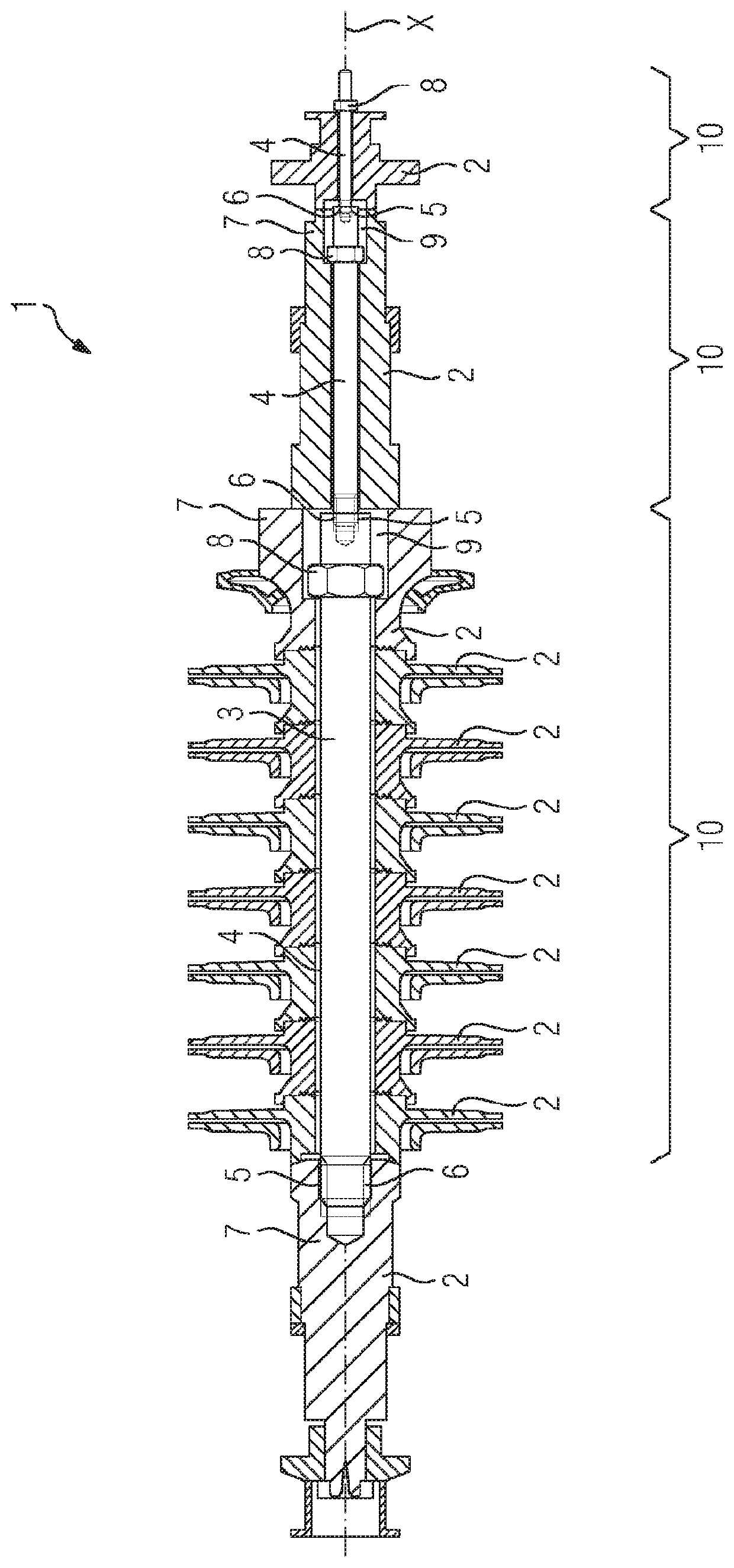
[0027]FIG. 1 shows a rotor 1 for a turbomachine (not illustrated), which rotor can be installed for example as a compressor rotor in a radial compressor. The rotor 1 comprises a plurality of rotor segments 2 which are arranged axially adjacent to one another. The rotor segments 2 have Hirth toothings and are each provided with a central opening through which a single tie rod 3 extends. The tie rod 3 comprises a plurality of tie rod sections 4 which are arranged axially adjacent to one another. The tie rod sections 4 are of cylindrical form, wherein, starting from one end of the tie rod 3, the cylinder diameters of the tie rod sections 4 decrease in a stepwise manner with a stepped outer contour being formed. Adjacent tie rod sections 4 are connected to one another by way of a screw connection. Here, in each case one tie rod section 4 has an axially extending threaded bore 5 into which an outer thread 6 formed at a free end of the adjacent tie rod section 4 is screwed. It goes withou...


PUM


Abstract

A rotor for a turbomachine, includes a plurality of axially adjacently arranged rotor segments which are each provided with a central opening, an individual tie rod extending through the openings of the rotor segments, and two holding devices which are arranged on axially opposing ends of the tie rod and hold the rotor segments together, the rotor segments forming at least two rotor segment groups between which at least one other holding device is arranged.

Description

CROSS REFERENCE TO RELATED APPLICATIONS[0001]This application is the US National Stage of International Application No. PCT / EP2016 / 078306 filed Nov. 21, 2016, and claims the benefit thereof. The International Application claims the benefit of German Application No. DE 102015225428.3 filed Dec. 16, 2015. All of the applications are incorporated by reference herein in their entirety.FIELD OF INVENTION[0002]The invention relates to a rotor for a turbomachine, comprising a plurality of rotor segments which are each provided with a central opening and are arranged axially adjacent to one another, a single tie rod which extends through the openings of the rotor segments, and two bracing means which are arranged at axially opposite ends of the tie rod and brace the rotor segments against one another.BACKGROUND OF INVENTION[0003]Rotors of said type are known in the prior art in a variety of configurations and serve for converting forms of energy into one another in turbomachines. For exampl...

Claims


Application Information

Patent Timeline
Patent Type & Authority Patents(United States)
IPC IPC(8): F01D5/06F04D17/12F04D29/054F01D5/02F04D29/62
CPCF04D29/624F04D17/122F01D5/026F04D29/054F01D5/066F05D2230/51F05D2260/96F05D2240/60F05D2260/31
Inventor JAHRMARCHT, STEFFENMINY, KEVIN
Owner SIEMENS ENERGY GLOBAL GMBH & CO KG
Why Eureka
Try Eureka