Device for separating liquids from gases

A gas and liquid technology, applied in the direction of engine components, machines/engines, mechanical equipment, etc., can solve the problems of large installation space and increased complexity, and achieve the effect of simple structure

Active Publication Date: 2009-08-12
POLYTEC PLASTICS GERMANY
View PDF2 Cites 3 Cited by
  • Summary
  • Abstract
  • Description
  • Claims
  • Application Information

AI Technical Summary

Problems solved by technology

[0004] The integration of the cyclone separator in the bonnet inevitably increases its complexity and requires a relatively large installation space

Method used


Image

  • Device for separating liquids from gases
  • Device for separating liquids from gases
  • Device for separating liquids from gases

Examples


Embodiment Construction

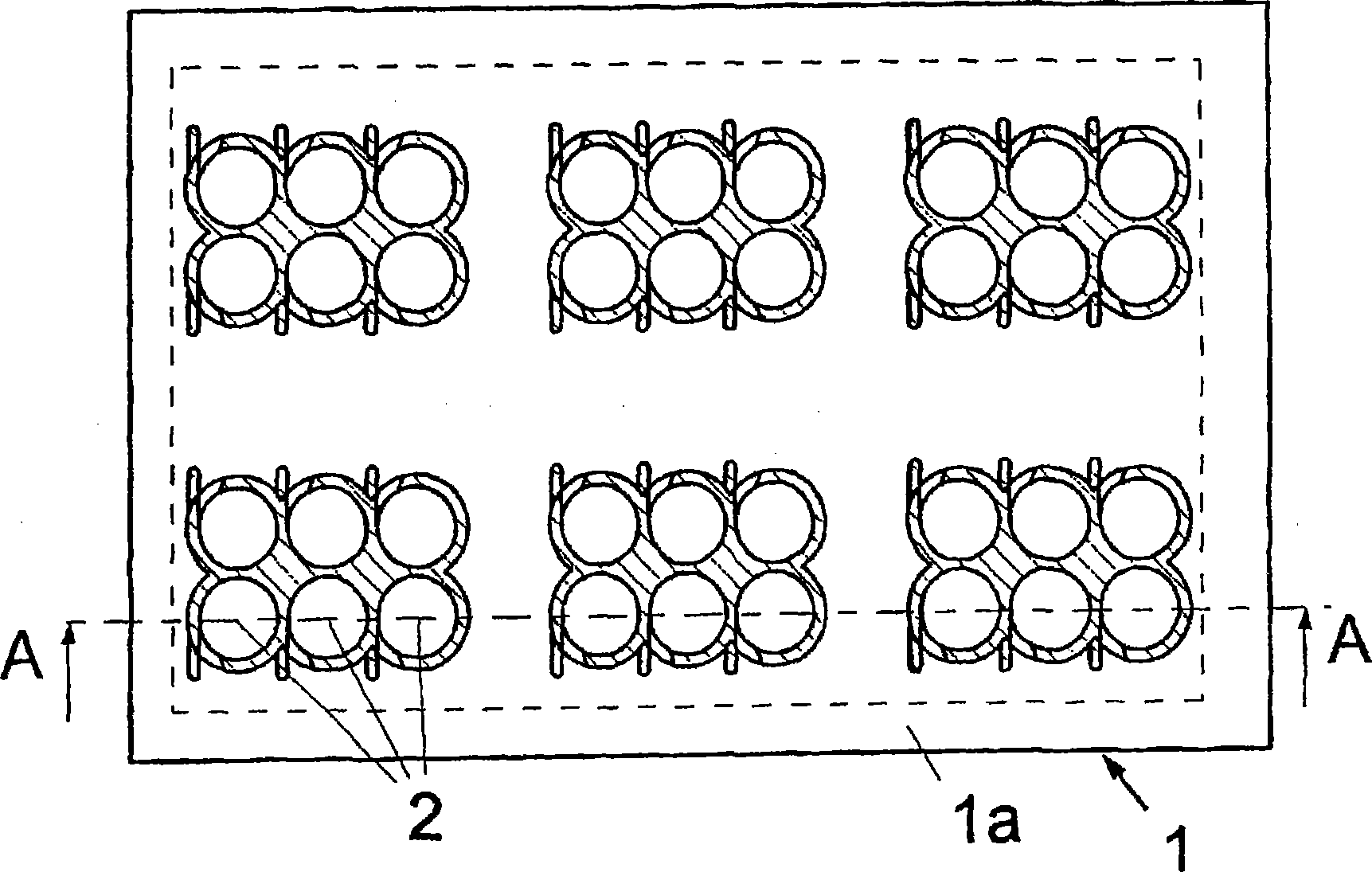
[0034] figure 1 The shown base 1 is designed as a plate-like plastic component with a large number of small integrally formed flow tubes 2 . The plate base 1 has a peripheral edge 1a. The base 1 has, for example, 30 to 40 flow tubes 2 arranged next to each other or in groups. The flow tube 2 has, for example, an inner diameter D of 5 mm and a length of 10 to 20 mm. exist figure 1 In the illustrated embodiment, six groups of six flow tubes 2 are provided.

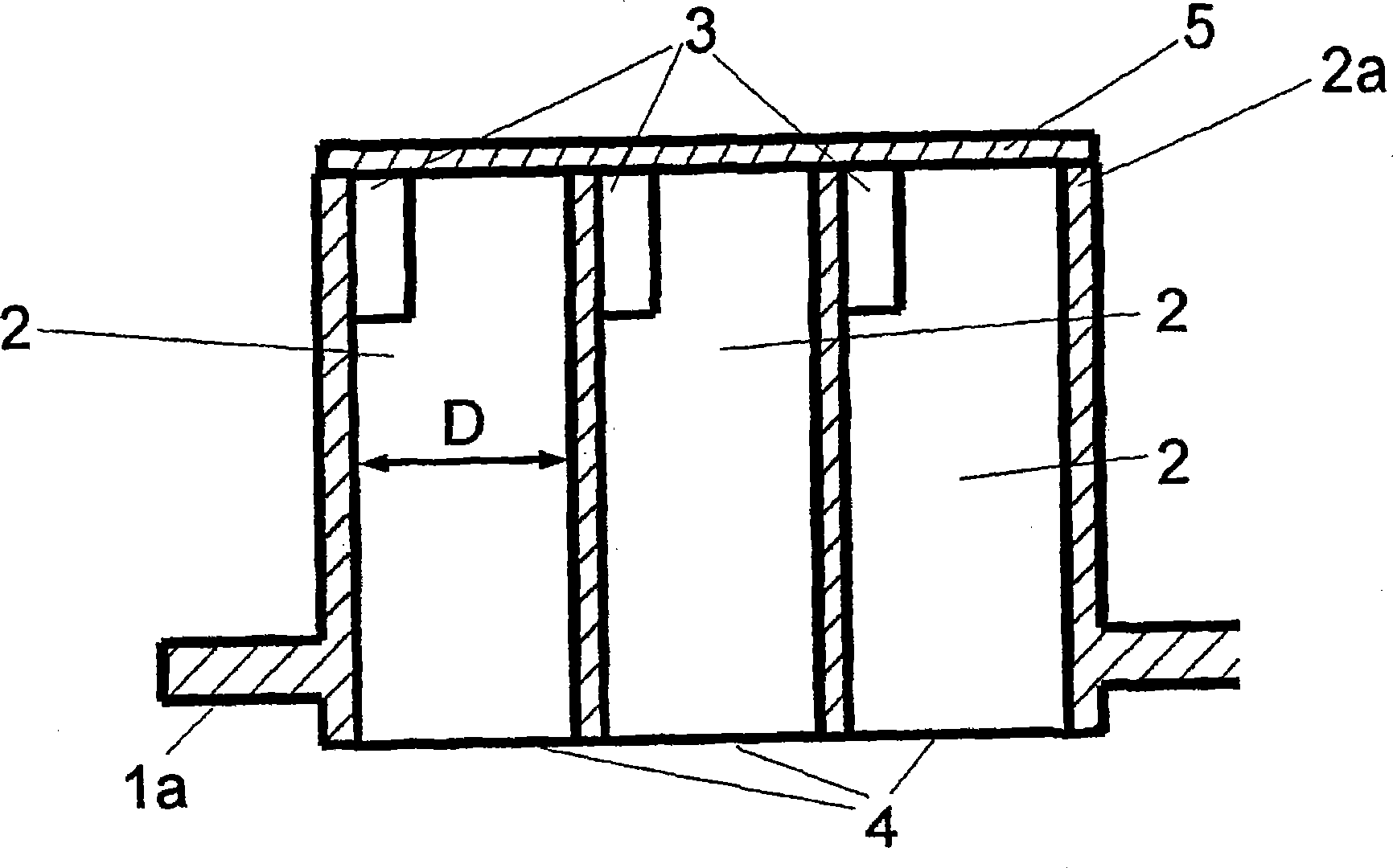
[0035] figure 2 A cross-section of a group with six flow tubes 2 is shown. Each flow tube 2 has a tangential feed gas inlet 3 and a gas outlet 4 through which clean gas and separated liquid flow out. The gas outlet 4 is almost on the same plane as the base 1 . Each flow tube 2 of equal length is closed at its end facing the gas inlet direction, at the front side 2a, by a cover plate 5 attached as shown in the exemplary embodiment. If the base 1 is made of plastic, the cover plate 5 can also be integrally molded to t...


PUM


Abstract

The invention relates to a device for separating liquids from gases, particularly for separating oil particles from blow-by-gases of crankcase vents of combustion engines. Considering the known disadvantages of the known state of the art, a device is proposed, characterized by a simple, cost effective and compact design and having a good deposition performance. The solution proposed, comprises single flow tubes 2 having at least on tangentially arranged gas input opening 3 at the end facing the gas input direction and at the adjoining face side 2a are closed off by a cover 5, wherein in the flow tubes 2 a combined rotation- and axial stream with a swirling component is developed and the rotation flow in the individual tubes 2 rotates several times at 360 DEG . The individual flow tubes 2 are part of a basic carrier, having a surrounding edge 1a. The basic carrier comprises for example 30 to 40 flow tubes 2, being adjacent to each other or are arranged in groups. The flow tubes 2 have an internal diameter D of for example 5 mm and a length of 10 to 20 mm. Due to the tangential input, the gas flow reaches higher rotary frequencies and higher centrifugal forces are present. The device can be configured as a very small, effective component, requiring only a small installation space.

Description

technical field [0001] The present invention relates to a device for separating liquids from gases, and in particular to a device for separating oil particles from leakage gases of crankcase ventilation devices of internal combustion engines. Background technique [0002] For example, for deoiling crankcase ventilation gas, cyclones of various configurations are known, such as single-stage or multi-stage cyclones. Gases collected in the crankcase laden with oil droplets are introduced tangentially into the cyclone separator. Due to the centrifugal force acting in the cyclone, the oil contained in the gas flow is deposited on the inner wall of the cyclone, and is supplied to the crankcase or oil sump of the internal combustion engine through an outlet provided at the bottom of the cyclone. The airflow is deflected in the cyclone, exits as pure gas through a dip tube arranged on top of the cyclone, and reaches the intake manifold of the engine. Single-stage cyclones have a l...

Claims


Application Information

Patent Timeline
Patent Type & Authority Applications(China)
IPC IPC(8): F01M13/04
CPCF01M13/0416F01M2013/0427
Inventor H·扬森J·苏亚雷斯T·布尔克特
Owner POLYTEC PLASTICS GERMANY
Why Eureka
Try Eureka