Brake system

a technology of brake cooling system and brake actuation mechanism, which is applied in the direction of brake system, aircraft brake actuating mechanism, mechanical apparatus, etc., can solve the problems of existing cooling system, maintenance and safety issues, and limit the rapid rotation of aircraft, so as to achieve global speed, reduce the cooling time of brakes, and improve braking. the effect of

Active Publication Date: 2018-08-02
COMMISSARIAT A LENERGIE ATOMIQUE ET AUX ENERGIES ALTERNATIVES
View PDF18 Cites 2 Cited by
  • Summary
  • Abstract
  • Description
  • Claims
  • Application Information

AI Technical Summary

Benefits of technology

[0023]The cooling is therefore globally faster and the brake can operate in the range of temperature wherein it is effective. The braking is consequently improved.
[0024]Particularly advantageously, the cooling device makes it possible to cool the brake even when stopped, i.e. when the rotor is not rotating.
[0025]Moreover, as the cooling time of brakes is substantially reduced, this allows for faster resumed use of the vehicles such as aircraft for example after an operating phase of the brake. The rotation frequency of aircraft is therefore improved thanks to the invention.
[0026]Furthermore the invention makes it possible to retain solid friction elements, typically solid discs without piercing. The invention therefore offers improved robustness in relation to brakes with pierced discs which is practice are very fragile.
[0027]Moreover, this invention is compact. Integrated into a wheel, this system represents only very little material added to the wheel. As such, in a field such as aeronautics or the automobile where the load is a key factor, using this invention is an advantage through its low weight. Its compactness allows it to be installed easily in current systems.
[0028]This invention has a certain advantage in terms of its adaptability relatively to various field of application. Indeed, whether in terms of its size and / or the materials used, it is possible to implement this invention in pre-existing brake systems.

Problems solved by technology

However, these existing cooling systems have many disadvantages.
In addition piercing holes in the carbon-carbon discs weakens them implying maintenance and safety issues.
In addition to these disadvantages, the cooling time for current brakes is long, typically from 30 minutes to 1 hour, thus implying a limitation to the rapid rotation of aircraft.

Method used


Image

  • Brake system
  • Brake system
  • Brake system

Examples


Embodiment Construction

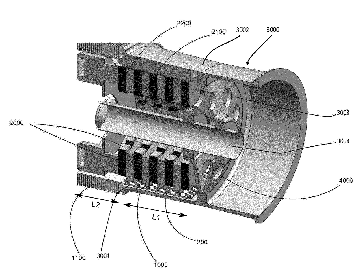
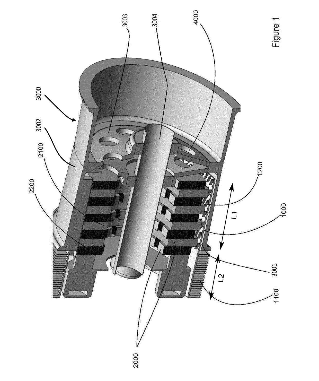
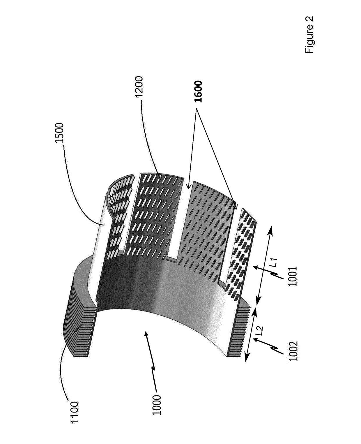
[0043]Before going into the details of the preferred embodiments in particular in reference to the figures, hereinafter various options are mentioned that preferably but not limitingly the invention can have, with these options able to be implemented, either separately, or according to any combination of them:[0044]Advantageously, the cooling device is separate from the body.[0045]Advantageously, the cooling device is secured to the body and added onto the body.[0046]Advantageously, the cooling device is secured to the body.[0047]Advantageously, the cooling device is added onto the body.[0048]Advantageously, the system comprises drive pins of the friction elements.[0049]As such, the cooling device is coupled in rotation with the plurality of discs secured to the rotor.[0050]This makes it possible to increase the, pressure of the ambient air on the first portion, as such increasing the thermal exchanges by convection between the discs and the cooling device.[0051]Advantageously, the ...


PUM


Abstract

According to an aspect, this invention relates to a cooling device for a disc brake, the device extending in a longitudinal direction and comprising a first portion configured to surround the discs of the brake, intended for being arranged facing the side surfaces of the brake discs and configured to capture, by irradiation and/or convection, the heat generated by the discs during the friction. The cooling device further includes a second portion, secured and thermally coupled to the first portion, offset in the longitudinal direction relative to the first portion, and provided with tins extending radially relative to the longitudinal direction and configured to dissipate the heat captured by the first portion, by convection and/or irradiation, into the ambient air.

Description

TECHNICAL FIELD OF THE INVENTION[0001]This invention relates to the field of brake systems and more particularly a brake cooling system. A particularly advantageous but non-limiting application is the field of brakes for wheels or axles for example of aircraft.PRIOR ART[0002]The cooling of brakes in the field of air transport is an important factor in the time allocated to each flight procedure. On aircraft, the cooling time of brakes is a major parameter of the safety protocols. Indeed, it is necessary for the temperature of the brakes to be less than a certain value before the aircraft is authorised to carry out a take-off procedure for example.[0003]Most of the current braking systems use carbon-carbon discs. Brake discs can reach temperatures of about 1000° C. during operation, however a drop in the temperature between 300° C. and 800° C. is required so that they can provide good braking.[0004]Cooling can be provided substantially when the vehicle is moving forward via ventilati...

Claims


Application Information

Patent Timeline
Patent Type & Authority Applications(United States)
IPC IPC(8): F16D65/847B60T5/00F16D65/12B64C25/42
CPCF16D65/847B60T5/00F16D65/128B64C25/42F16D2065/789B64C25/44
Inventor GRUSS, JEAN-ANTOINEDUCROS, FREDERIC
Owner COMMISSARIAT A LENERGIE ATOMIQUE ET AUX ENERGIES ALTERNATIVES
Why Eureka
Try Eureka