Use of a virtual clock in a PLL to maintain a closed loop system

Active Publication Date: 2020-07-28
SKYWORKS SOLUTIONS INC
View PDF19 Cites 13 Cited by
  • Summary
  • Abstract
  • Description
  • Claims
  • Application Information

AI Technical Summary

Problems solved by technology

Some systems use a single input reference clock signal and the loss of signal results in holdover.

Method used


Image

  • Use of a virtual clock in a PLL to maintain a closed loop system
  • Use of a virtual clock in a PLL to maintain a closed loop system
  • Use of a virtual clock in a PLL to maintain a closed loop system

Examples


Embodiment Construction

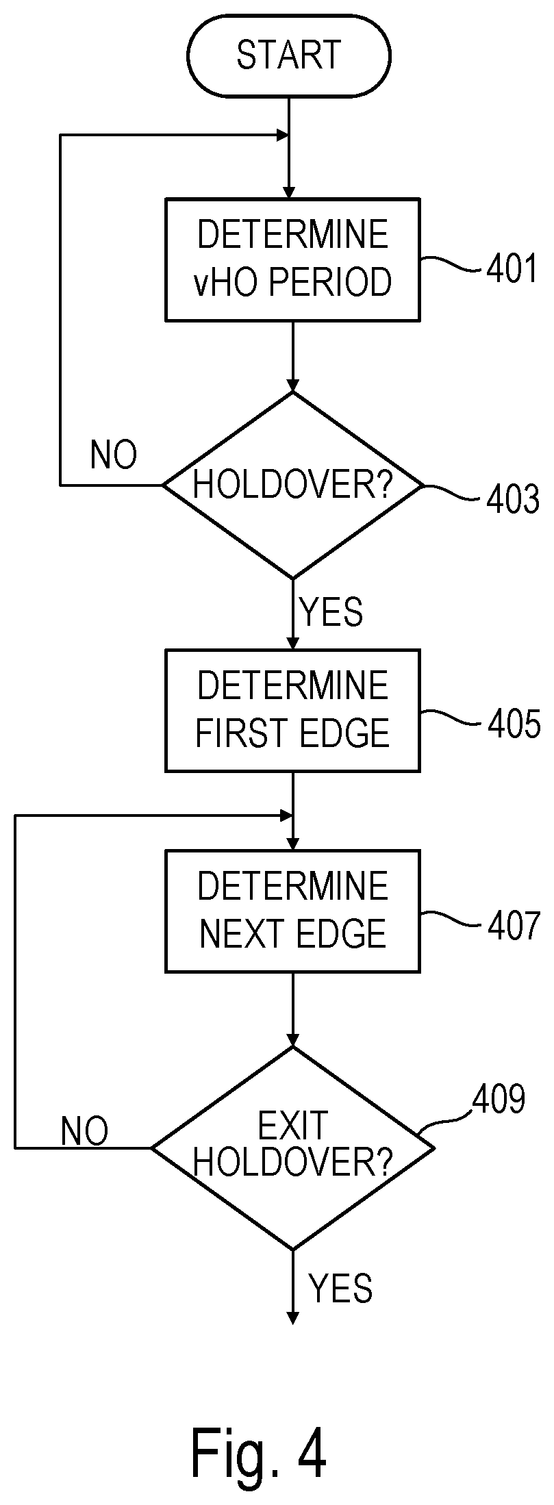
[0007]Accordingly, in one embodiment, a method includes using a virtual clock signal as a reference clock signal for a phase-locked loop, the virtual clock signal being a series of time stamps separated by a time period, the time stamps corresponding to respective transitions of the virtual clock signal and the time period corresponding to a period of the virtual clock signal.

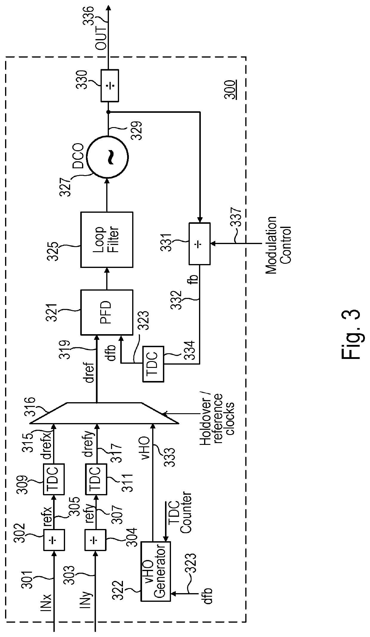
[0008]In another embodiment a phase-locked loop includes a virtual clock signal generator to supply a virtual clock signal, the virtual clock signal being a series of time stamps separated by a time period, the time stamps corresponding to respective transitions of the virtual clock signal and the time period corresponding to a period of the virtual clock signal. A selector circuit selects the virtual clock signal as a reference clock signal instead of a second reference clock signal for use by a phase and frequency detector of the phase-locked loop. The second reference clock signal is based on an input refere...


PUM


Abstract

A PLL uses a virtual clock signal during holdover and / or startup to maintain a closed loop for the PLL and allow for phase / frequency adjustment of the PLL output through the feedback divider during holdover / startup when reference clock(s) supplied to the PLL are unavailable. The virtual clock signal is a series of digital values separated by a time period, where the digital values indicate transitions of the virtual clock signal and the time period corresponds to a period of the virtual clock signal. A selector circuit selects as a digital reference clock signal the virtual clock signal in a holdover or startup mode and another reference clock signal in normal operation.

Description

BACKGROUNDField of the Invention[0001]The description herein relates to phase-locked loops (PLL) and more particularly to use of a virtual clock in PLLs.Description of the Related Art[0002]FIG. 1 illustrates a high level block diagram of a typical phase-locked loop (PLL) 100 that has the ability to switch between reference clock signals INx 101 and INy 103 to generate a PLL output signal OUT 105 that is phase locked to the currently selected reference clock signal. The PLL works by continuously comparing the phases of the feedback (fb) clock signal 107 and the reference clock signal (ref) 109 in the phase and frequency detector (PFD) 111 and adjusting the phase of OUT 105 to keep OUT phase aligned to the selected reference clock signal. Output divider 115 (the R divider) divides the output 118 of the digitally controlled oscillator (DCO) 119 to generate OUT 105. Feedback divider 117 divides the output 118 of the DCO 119 to generate the feedback signal 107.[0003]Some applications req...

Claims


Application Information

Patent Timeline
Patent Type & Authority Patents(United States)
IPC IPC(8): H03L7/099H03L7/093
CPCH03L7/099H03L7/093H03L7/08H03L7/18H03L7/143H03L7/183
Inventor BALAKRISHNAN, KRISHNANBARNETTE, JAMES D.
Owner SKYWORKS SOLUTIONS INC
Why Eureka
Try Eureka