Shoulder transfer weight support

a shoulder and support technology, applied in the field of medical devices, can solve the problems of limiting workers' comfort while working, and achieve the effects of reducing pressure on the cervical spine, reducing contact and stress, and reducing weight and pressur

Active Publication Date: 2020-08-04
G TECH LLC
View PDF12 Cites 2 Cited by
  • Summary
  • Abstract
  • Description
  • Claims
  • Application Information

AI Technical Summary

Benefits of technology

[0008]The present invention is a fixed-angle, wearable device that supports the weight of a heavy garment, such as a lead apron or other heavy garment and transfers the weight of the garment that would normally be supported by the wearer's shoulders to the wearer's hips. The device eliminates contact and stress on the wearer's shoulders cervical spine. The device allows a wearer to wear a heavy garment, such as a lead apron or shield, while protecting their shoulders and spine from having to support excess weight. By transferring the weight off of the shoulders, there is also less pressure on the cervical spine as many radiologic procedures require the wearer bend forward for significant periods of time. At the same time, the device also helps to correct the wearer's posture and to support their lower back to alleviate weight and pressure that over time can cause lower back injuries. The anatomic contour of the device provides lumbar support and promotes optimal ergonomic posture. Surgeons in particular will benefit from the use of this device as it allows them to wear heavy garments during lengthy surgical procedures without straining or risking injury to their spines. The device also creates space between the wearer's body, particularly their shoulders and the backs, and as a result, helps to provide ventilation to the wearer while they are wearing a heavy garment. The weight and heat encountered by surgeons and other medical professionals that have to wear radio-opaque garments severely limits their comfort while working.
[0013]In addition, the upper back plate can feature a second set of drilled holes positioned such that when the shoulder extension(s) are attached to the upper back plate they can be moved laterally with respect to the wearer's shoulders if desired. Laterally here means the shoulder supports can be positioned closer or father away from the wearer's head. The drilled holes on the shoulder supports and upper back plate also make it possible to reposition the shoulder extensions at different heights above the user's shoulders. It is anticipated that the shoulder extensions will be attached and positioned such that the shoulder extensions stay about ¾ of an inch above the user's shoulders. However, as discussed, the height of the shoulder extensions can be modified as the wearer deems useful.
[0014]Preferred embodiments of the invention feature a hinge that allows the upper half of the device to fold down over the lower half of the device to make the device easier to carry or store. The device folds ventrally, which is to say that the upper portion of the device folds downward toward where the user's waist would be until it contacts the lower portion of the device. The hinge can be any standard hinge known in the prior art, but preferred embodiments of the invention include a slip-hinge with a bore and a pin that inserts into the bore to lock the hinge in position. More specifically, the hinge consists of a knuckle, a pin, an upper leaf and a lower leaf. The upper leaf features drilled holes or other attachment means that allow the upper leaf to connect to the upper attachment bar, or alternately to the upper back plate itself. The lower leaf attaches to the lower or second attachment bar or the lower back plate. Each of the upper and lower leaves features a bore positioned such that when the upper and lower leaves are fully extended and the devices is in an “unfolded” or “open” state, the bores align such that a pin or other object can be inserted into each bore, locking the leaves in place with respect to each other and the rest of the device. In preferred embodiments and the anticipated best mode of the device, the lower leaf features a shelf or indention that is complementary to at least a portion of the upper leaf. When the device is unfolded (the upper half and lower portion are moved dorsally or away from each other) for use, the upper leaf contacts this shelf on the lower leaf preventing the upper leaf, and the upper portion of the device, from moving any further (dorsally). In addition, when in this position, the bores on the upper leaf and lower leaf align allowing for the insertion of a pin into the bores, thereby locking the two leaves in place and locking the device in an “open” or “unfolded” position. In preferred embodiments of the invention, the pin has a ring attached to it making it easy to pull out of the bores when the device is to be folded.
[0017]In use, the wearer puts the device on their back and secures the hip belt around their waist. Then the lead apron or other garment is attached to the device such that the garment is worn over the device. The shoulder extensions can fit into sleeves featured by the garment—the typical lead apron used by medical professionals often has sleeves already integrated into it. In addition, the protrusions or pins on the shoulder supports can be positioned to fit into or through holes featuring grommets in the garment to help hold the garment in place. When the hip belt is secured around the waist, and the garment is attached or draped over the device, the weight of the garment does not rest on the wearer's shoulders or spine, but is transferred to their hips. The lower and upper back plates are shaped such that the device, when the wearer stands upright, does not contact the user's back, neck or shoulders. A space between the user and the heavy garment is created by the device that allows air entering (through the sides or top of the apron or garment) to circulate and keep the wearer cooler than they would be if they wore the garment against their person. The device thereby allows the wearer to perform lengthy medical procedures, even those that require bending over the patient for prolonged periods of time, without having to support the weight of the required radio-opaque garments with their shoulders or backs.
[0018]The inventive weight support allows the user to use / wear heavy shielding garments without obstructing the function of those garments. The invention allows a user to wear various types of heavy clothing or equipment without interfering with the normal movements of the wearer. The device also provides lumbar support and improves body ventilation for those wearing heavy shielding garments. By transferring weight away from the shoulders, the device reduces the incidence of cervical orthopedic injury sustained by the user. By providing lumbar support to the user, the weight support also results in improved posture and reduces the incidence of lower back strain and injury. Moreover, because the weight support creates some separation between the clothing and the user, the weight support serves to provide additional ventilation that is not available when the user wears the same clothing or equipment directly against their body. The device is light weight, comfortable, durable, easy to clean, and easy to put on or remove. In addition, since the device is not integrated into a garment, the device can be used with more than one garment including a “half-garment” that is meant to be worn only over front of the wearer. In such embodiments, the back support and other components of the device can be made of or infused with radio-opaque materials to help increase the shielding provided by the garment.

Problems solved by technology

The weight and heat encountered by surgeons and other medical professionals that have to wear radio-opaque garments severely limits their comfort while working.

Method used


Image

  • Shoulder transfer weight support
  • Shoulder transfer weight support
  • Shoulder transfer weight support

Examples


Embodiment Construction

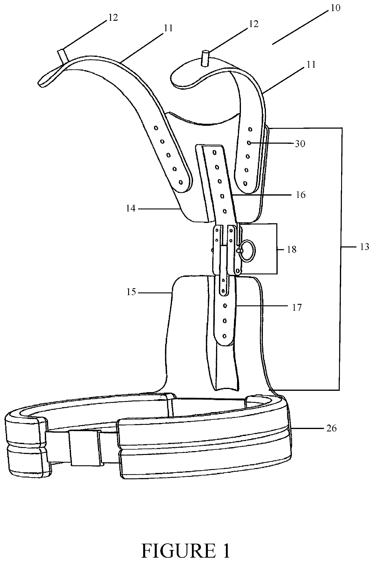
[0026]Referring now to the invention in more detail, FIG. 1 shows a perspective view of the device, generally 10, in an “unfolded” or “open” state. The device or frame includes two shoulder extensions 11 that are elongated, rigid bars that are shaped such that, when attached to the device 10, they are positioned to extend up and over a wearer's shoulders. In preferred embodiments and the anticipated best mode of the device 10, the shoulder extensions 11 feature pins 12 protruding from an upper surface of the shoulder extensions 11, away for the wearer. As previously discussed, these pins can be used to support other equipment, including a face shield. In addition, the shoulder extensions 11 are attached to a back support, generally 13. The back support 13 is generally made of one or more back plates. In the embodiment shown in the drawings, the back support consists of an upper back plate 14, a lower back plate 15, an upper attachment bar 16, a lower attachment bar 17 and a hinge 18...


PUM


Abstract

A wearable weight support that transfers the weight of heavy garments that rely on shoulder support, off of the shoulders to the hips of the user. The device provides additional posterior radiation protection to the wearer as the back support can be made from radio-opaque materials. The device also provides lumbar support and results in less body heat containment through natural venting. The device is easily adjustable to any body type and allows the wearer to move more freely in their work environment. The invention can be used to transfer the weight of a backpack or other systems which rely on shoulder support to function.

Description

CROSS-REFERENCE TO RELATED APPLICATIONS[0001]This Application claims the benefit of priority to U.S. Provisional Application No. 62 / 458,623 filed on Feb. 14, 2017. The content of U.S. Provisional Application No. 62 / 458,623 filed on Feb. 14, 2017 is incorporated by reference in its entirety.BACKGROUND OF THE INVENTION(a) Field of the Invention[0002]The present invention is in the technical field of medical devices. More particularly, the present invention is in the technical field of support devices to be worn by medical professionals conducting procedures involving exposure to radiation.(b) Background Art[0003]There are several occupations which require personnel to wear heavy clothing and / or to attach heavy items to their clothing, including heavy shielding garments. For example, in the medical field, personnel are required by law to protect themselves from excessive radiation exposure in order to reduce their lifetime risk for life threatening illnesses. In military and law enforc...

Claims


Application Information

Patent Timeline
Patent Type & Authority Patents(United States)
IPC IPC(8): A41F19/00G21F3/02A41D13/015
CPCG21F3/02A41F19/00A41D13/015
Inventor TRUELOVE, III, LEROYBUCHANAN, WILLIAMMOORE, JR., RICHARD S.
Owner G TECH LLC
Why Eureka
Try Eureka