Ramp door with self-deploying rail

a self-deploying rail and door technology, applied in the direction of doors, loading/unloading vehicle arrangment, transportation items, etc., can solve the problem of time-consuming tasks, and achieve the effect of convenient loading and unloading of items

Active Publication Date: 2020-08-04
LIPPERT COMPONENTS
View PDF13 Cites 6 Cited by
  • Summary
  • Abstract
  • Description
  • Claims
  • Application Information

AI Technical Summary

Problems solved by technology

These tasks may be time-consuming and may require two or more persons to accomplish.

Method used


Image

  • Ramp door with self-deploying rail
  • Ramp door with self-deploying rail
  • Ramp door with self-deploying rail

Examples


Embodiment Construction

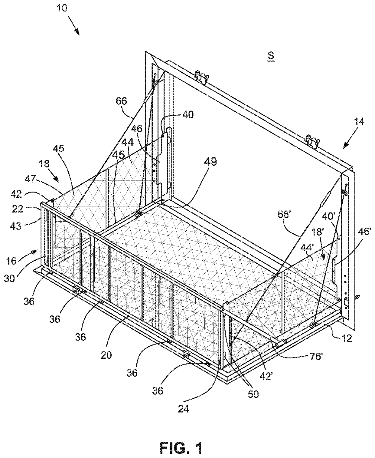
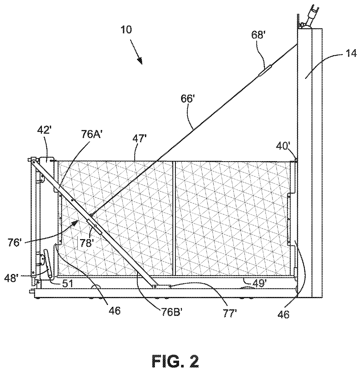
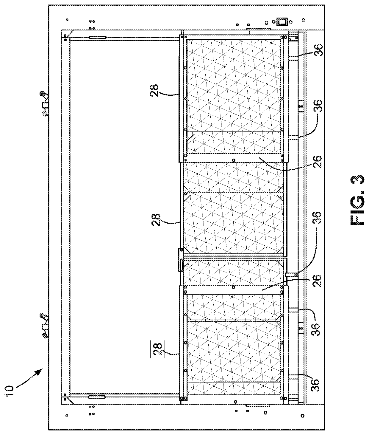
[0019]The drawings show illustrative embodiments of a system 10 including a ramp door 12 pivotable with respect to a structure S, for example, an RV, a rail (or barrier) system pivotally attached to the ramp door, and an operating mechanism operable, in response to pivoting of the ramp door, to reposition portions of the rail system between a first (or collapsed) position in which the portions of the rail system are generally collapsed against the ramp door and a second (or deployed) position in which the portions of the rail system are generally perpendicular to the ramp door.

[0020]The ramp door 12 is shown as a panel P having a first (or connected or pivot) end pivotally attached to a door frame or hoop 14, a second (or free) end opposite the connected end, and first and second (or left and right) opposed sides extending between the first end and the second ends. The hoop 14 is configured for attachment to the structure S. The pivotal connection of the ramp door 12 to the hoop 14 ...


PUM


Abstract

A ramp door and door frame include a rail kit that deploys automatically when the door is opened and collapses automatically when the door is closed. The door is supported by a cable mechanism when the door is opened. The cable mechanism causes an end rail to pivot up and away from the door when the door is opened and down and toward the door when the door is closed. The end rail cooperates with a door frame to deploy flexible side barriers when the door is opened and to collapse the side barriers when the door is closed.

Description

CROSS-REFERENCES TO RELATED APPLICATIONS[0001]This application claims the benefit of U.S. Provisional Patent Application No. 62 / 638,546, filed Mar. 5, 2018, the entire content of which is herein incorporated by reference.STATEMENT REGARDING FEDERALLY SPONSORED RESEARCH OR DEVELOPMENT[0002](NOT APPLICABLE)BACKGROUND AND SUMMARY[0003]A recreational vehicle (RV) may include a ramp door providing access between the interior of the RV and the environment about the RV. Such a ramp door typically is pivotally mounted to the RV proximate a floor thereof and pivotable about an axis parallel to and substantially flush with the floor. In a closed or stowed position, the ramp door may form a wall or a portion of a wall of the RV. For example, a ramp door may form a rear wall or a portion of a rear wall of an RV when closed.[0004]The ramp door may be opened or deployed to a ramp position wherein the free end of the ramp door is adjacent the ground upon which the RV is parked. In this position, t...

Claims


Application Information

Patent Timeline
Patent Type & Authority Patents(United States)
IPC IPC(8): B60J5/10B60P3/34E04F11/18B60P1/43
CPCB60J5/107E04F11/18B60P1/435B60J5/102B60P3/34
Inventor ROTH, BRYAN J.PEACHEY, KEVINOTTO, JEREMIAHBRADLEY, JEREMIAH R.
Owner LIPPERT COMPONENTS
Why Eureka
Try Eureka