
Supporting wheel device used for cabling machine

A cable forming machine and roller technology, which is applied in cable/conductor manufacturing, electrical components, circuits, etc., can solve the problems of high labor intensity for adjustment, time-consuming and laborious installation, etc., and achieves reduced labor intensity, high bearing strength and high stability. Effect

Active Publication Date: 2014-10-15
PINGHU DIGONG MACHINERY MFG
View PDF7 Cites 5 Cited by
  • Summary
  • Abstract
  • Description
  • Claims
  • Application Information

AI Technical Summary

Problems solved by technology

[0004] The purpose of the present invention is to provide a supporting roller device for cable forming machine, which can effectively solve the problems of high labor intensity in adjusting the existing supporting roller device and time-consuming and labor-intensive installation.

Method used


Image

  • Supporting wheel device used for cabling machine
  • Supporting wheel device used for cabling machine
  • Supporting wheel device used for cabling machine

Examples


Embodiment Construction

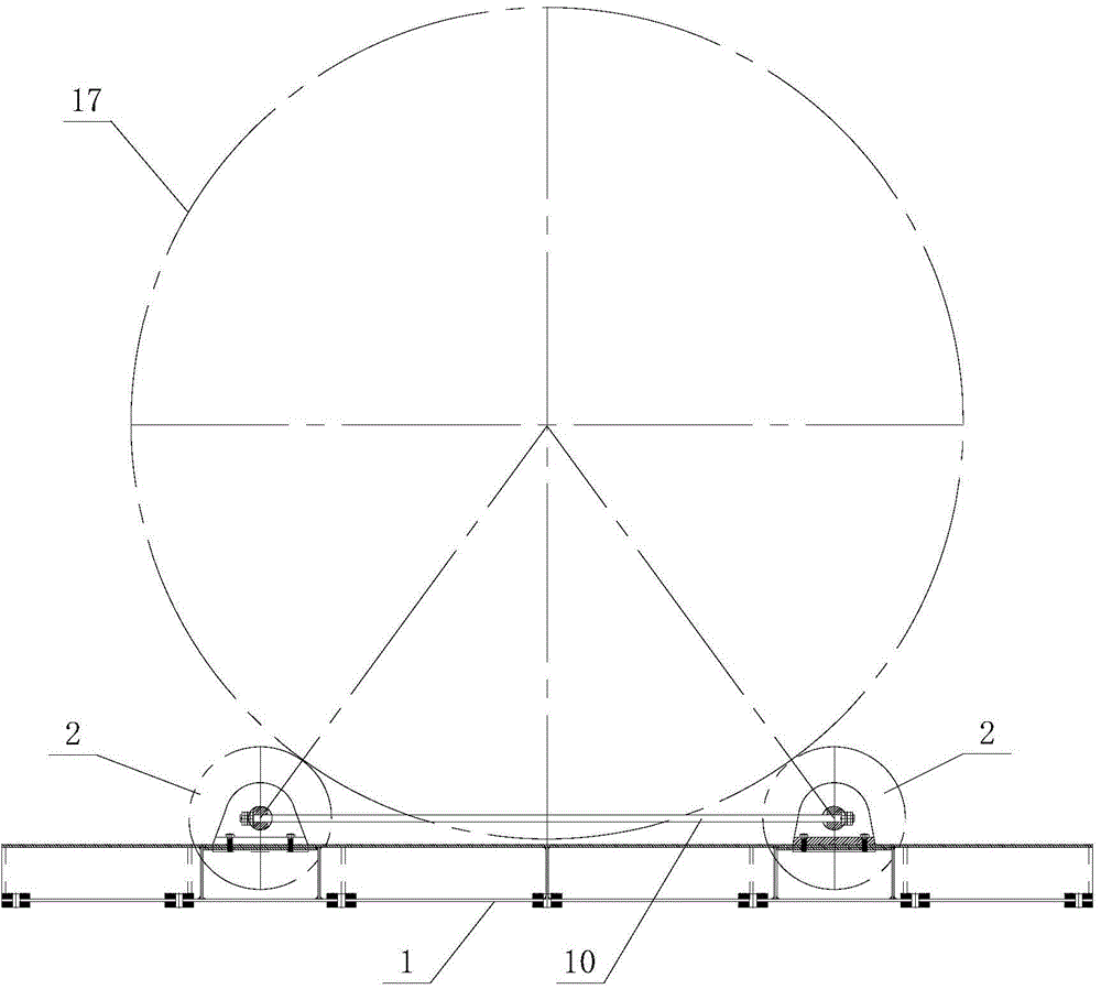
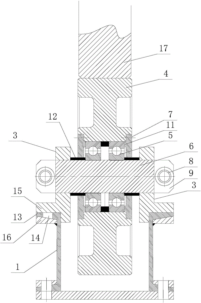
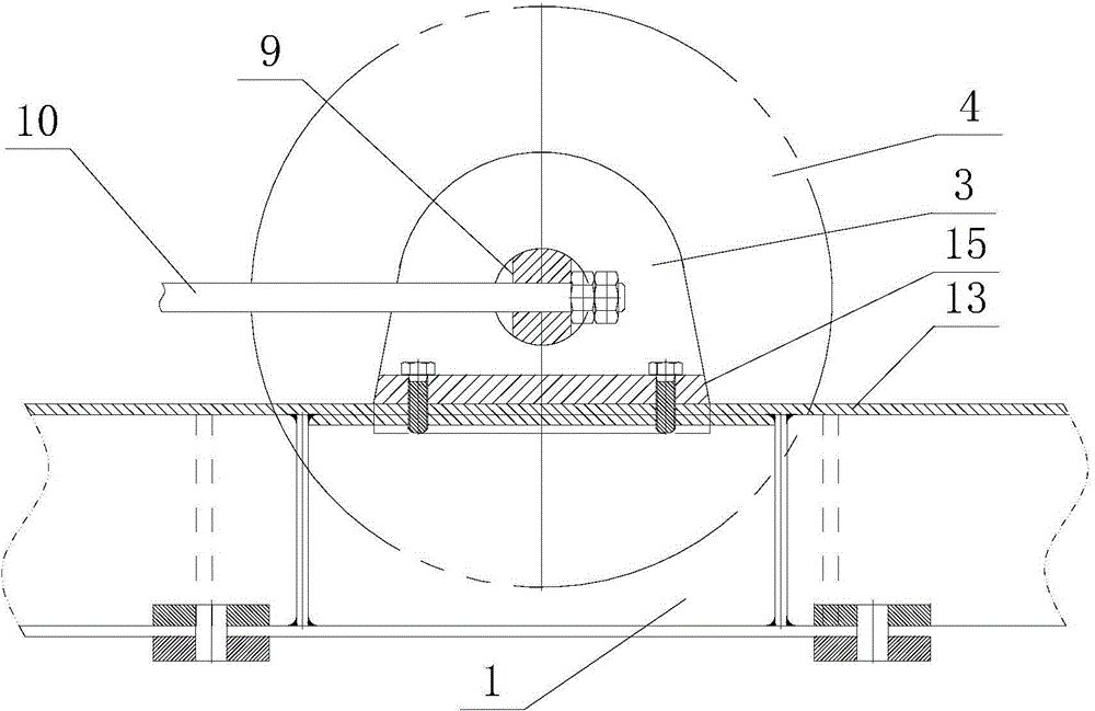
[0012] refer to figure 1 It is an embodiment of a supporting wheel device for a cable forming machine of the present invention, a supporting wheel device for a cable forming machine, comprising an underframe 1, two groups of supporting wheel assemblies 2 arranged on the underframe 1, such as figure 2 , image 3 As shown, each set of supporting wheel assemblies 2 includes two supports 3 fixed on the chassis 1, and a supporting wheel 4 arranged between the two supports 3, and the supporting wheels 4 are sleeved on the On the rotating shaft 6, the rotating shaft 6 on both sides of the bearing 5 is also provided with a transparent cover 7, and the position corresponding to the outer ring of the bearing 5 on the described transparent cover 7 is provided with a ring of bosses 11, and the transparent cover 7 and the supporting wheel 4. It is fixed by bolts. A sealing ring 12 is provided between the transparent cover 7 and the rotating shaft 6. The two ends of the rotating shaft 6 p...


PUM


Abstract

The invention discloses a supporting wheel device used for a cabling machine. The supporting wheel device comprises a chassis and two set of supporting wheel assemblies arranged on the chassis; each supporting wheel assembly comprises two supporting seats which are fixed on the chassis and a supporting wheel arranged between the two supporting seats; each supporting wheel sleeves a rotating shaft through a bearing; the rotating shaft is provided with penetrating covers which are located at two sides of the bearing; two ends of the rotating shaft respectively extend out from corresponding supporting seats; through holes are formed in portions of the rotating shaft which extend out from the supporting seats; the rotating shaft is provided with two fixing planes which are located at two ends of the through holes; through holes at the same side of the rotating shaft of each set of supporting wheel assembly are connected with each other through a connecting rod; and two ends of the connecting rod are respectively provided with a screw thread. According to the supporting wheel device of the invention, through the effect of the connecting rod, one set of supporting wheel assembly can be adjusted, and thereafter, the other set of supporting wheel assembly can be pulled to the center through the connecting rod until acting forces at two sides of the connecting rod are balanced, and contact surfaces are fittingly attached to each other, and therefore, labor intensity of installation personnel can be reduced, time and labor can be saved; and after installation, operational stability of equipment is higher, and noises are low, and the bearing strength of the installed supporting wheels is larger.

Description

technical field [0001] The invention relates to a supporting wheel device for a cable forming machine. Background technique [0002] Existing supporting roller device mainly is made up of parts such as supporting roller, rotating shaft, bearing, underframe, and this device is mainly used on the cable-forming machine, is installed in the cable-forming machine winch cage below. After the supporting wheels on both sides are fixed, hold up the winch. During the operation of the winch cage, the supporting wheels also rotate together to provide support for the winch cage and make the winch cage run stably. [0003] The existing support roller device is separate, and the fine adjustment of the gap between the support roller and the winch is realized by adjusting the screw rod at the rear of the support. When the cable forming machine is installed, it is necessary to repeatedly adjust the support rollers on both sides, which is labor-intensive and time-consuming and labor-intensive...

Claims


Application Information

Patent Timeline
Patent Type & Authority Applications(China)
IPC IPC(8): H01B13/00
Inventor 陆兴观
Owner PINGHU DIGONG MACHINERY MFG
Learn More