
Determination of hydronic valve opening point

a technology of hydronic valve and opening point, which is applied in the direction of heating types, program control, instruments, etc., can solve the problem that the controller assembly may not be able to control water flow over a full range of flow ra

Active Publication Date: 2020-08-11
COMPUTIME LTD
View PDF6 Cites 0 Cited by
  • Summary
  • Abstract
  • Description
  • Claims
  • Application Information

AI Technical Summary

Benefits of technology

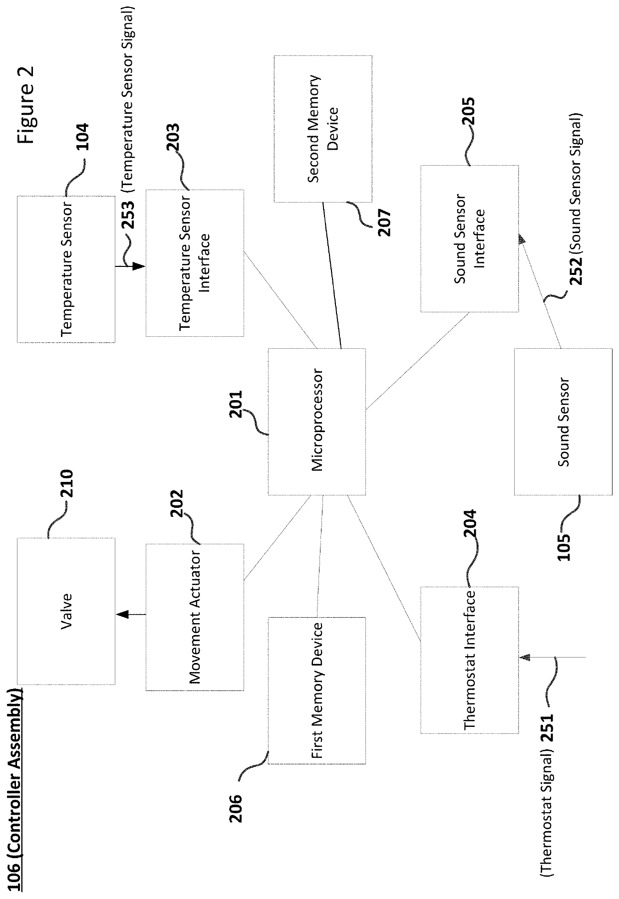
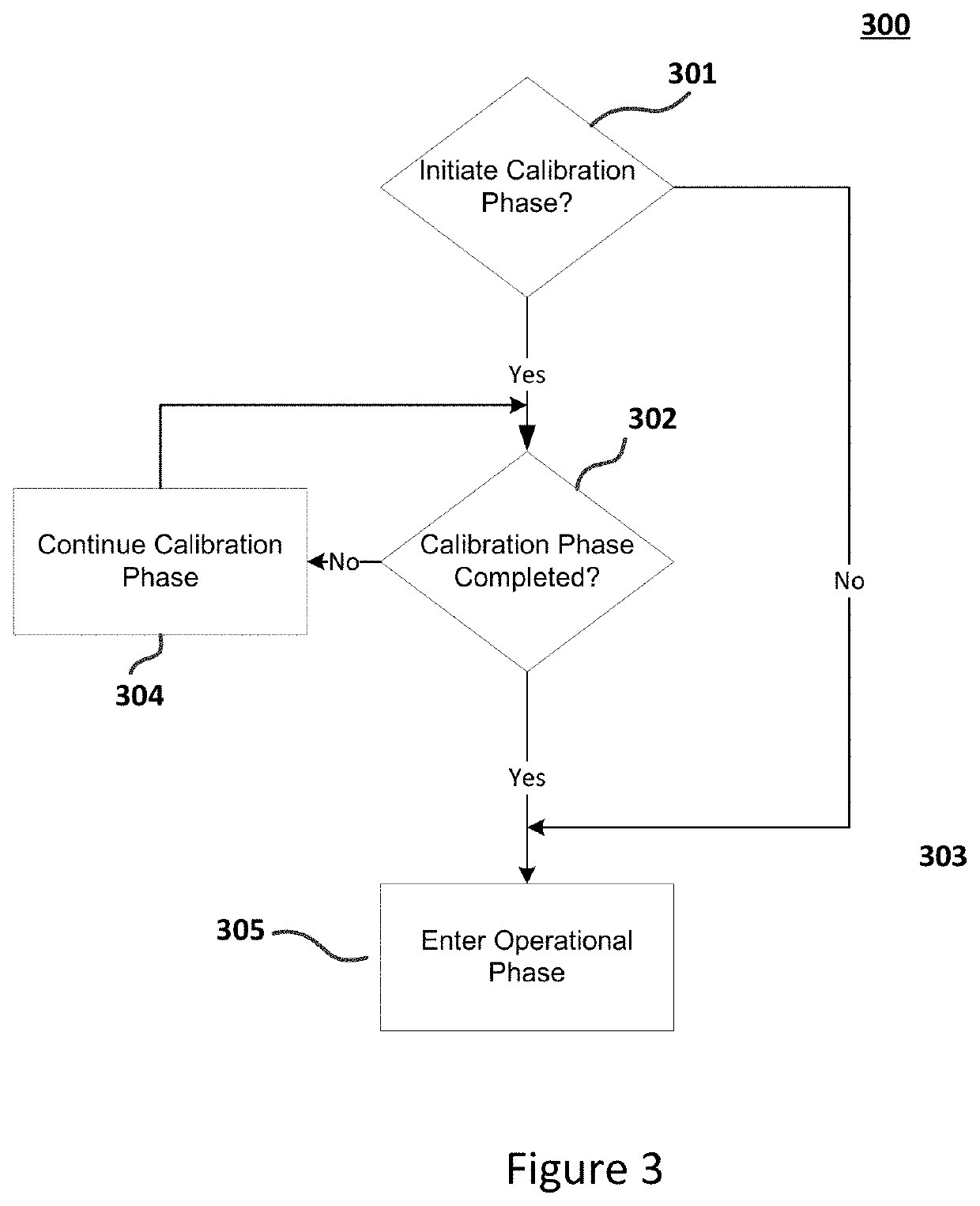
This patent is about a controller that can control the temperature of a room using a valve and hydronic emitter. The controller can calibrate the valve to control the minimum amount of water flow and detect the position at which the valve opens to allow water flow during the calibration phase. This position is then used during the operational phase to control the amount of water flow and achieve the desired temperature. The system can also perform multiple calibrations and store the position of the valve where the minimum water flow is detected. The technical effect of this patent is to provide a more accurate and efficient way to control the temperature of a room using a hydronic emitter system.

Problems solved by technology

Without this discovered start point, as may be the case with traditional approaches, the controller assembly may not be able to control water flow over a full range of flow rate when in an operational phase.

Method used


Image

  • Determination of hydronic valve opening point
  • Determination of hydronic valve opening point
  • Determination of hydronic valve opening point

Examples


Embodiment Construction

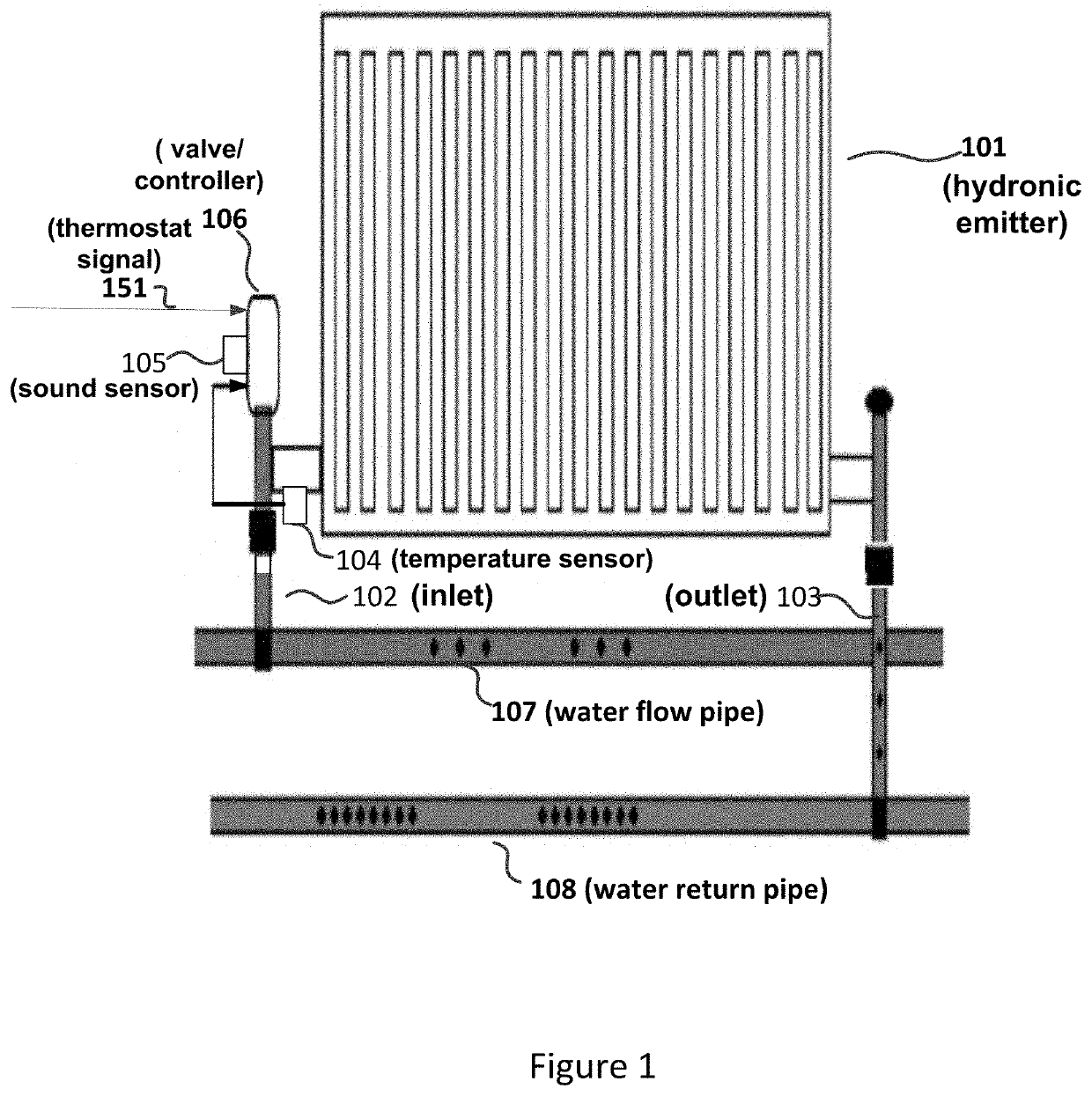
[0019]According to an aspect of the embodiments, a controller assembly of a heating / cooling system supports a calibration phase that discovers a point at which a particular valve starts to allow water flow (corresponding to an essentially minimum water flow) through a hydronic emitter. The point where water starts to flow typically varies for different valves even with the same manufacturer and batch. One reason is that water flow starts when the valve seal (for example, a rubber seal) starts to lift, where the occurrence of this event varies from one given valve to another. However, the variability across different valves is typically not as pronounced for a maximum water flow, which occur when the valve is fully opened. The above observation underscores the need for a calibration procedure (phase) to discover the positioning of the actual valve in the heating / cooling system when water starts to flow.

[0020]In accordance with the above observation, a fixed position for a valve / actua...


PUM


Abstract

A controller assembly allows an adjusted flow of water through a hydronic emitter in order to heat or cool an environmental entity. The controller assembly operates in two phases: a calibration phase and an operational phase. During the calibration phase, the controller assembly discovers a valve position where water starts to flow through the hydronic emitter based on signals from a temperature sensor and / or a sound sensor. The temperature sensor may be mounted in close proximity of the emitter inlet so that the controller assembly can detect when the temperature starts to change. The sound sensor may be mounted on the valve body to detect a rushing water sound that is associated with a start of the water flow. The discovered valve position is subsequently used by the controller assembly to adjust water flow between a minimum flow and a maximum flow.

Description

TECHNICAL FIELD[0001]Aspects of the disclosure relate to calibrating a controller assembly to control water flow through radiators, underfloor heating circuits, chilled beams or fan-coils for a heating / cooling system.BACKGROUND OF THE INVENTION[0002]Heating / cooling systems with hydronic emitters (including radiators, underfloor heating / cooling circuits, fan coils, chilled beams) are based on power transfer from one or more of the hydronic emitters to affect one or more environmental entities (for example, offices, apartments, conference rooms, and the like). However, traditional approaches do not sufficiently account for the variations of components of the heating / cooling system and consequently may not operate in an efficient manner.SUMMARY OF THE INVENTION[0003]An aspect supports a controller assembly that provides temperature room control using a high precision movement actuator fitted with an inlet temperature sensor and / or a sound sensor mounted on the associated valve body. Af...

Claims


Application Information

Patent Timeline
Patent Type & Authority Patents(United States)
IPC IPC(8): F24D19/10F24D3/12F24F5/00F24F11/00F16K37/00F24F11/84G05B19/042
CPCF24F5/0092F24F11/00G05B19/042F24F11/84F24D19/1015F16K37/0091F24D3/122F16K37/0083G05B2219/25312G05B2219/2648F24D2220/04F24D2220/042F24D2220/044G05D23/1931
Inventor SMITH, PHILIP JOHN
Owner COMPUTIME LTD
Learn More