Shaped charge liner, method of making same, and shaped charge incorporating same

a charge liner and shaped technology, applied in the direction of explosive charges, transportation and packaging, well accessories, etc., can solve the problems of reducing the permeability of the surrounding formation, limiting the eventual flow of oil/gas from the reservoir, and reducing the performance and/or non-geometric perforation holes, etc., to facilitate the reduction of recovery time

Active Publication Date: 2020-08-11
DYNAENERGETICS EURO GMBH
View PDF92 Cites 5 Cited by
  • Summary
  • Abstract
  • Description
  • Claims
  • Application Information

AI Technical Summary

Benefits of technology

[0010]According to an aspect, the present embodiments may be associated with a shaped charge liner. Such shaped charge liners may create ideal perforations for stimulation of the flow of oil / gas from oil reservoirs / wellbores, and uniform distribution of perforation tunnels that facilitate reduction in recovery time from the reservoirs.
[0013]Further embodiments of the disclosure are associated with a shaped charge having a case, an explosive load, and a shaped charge liner. The case has a plurality of walls including a side wall and a back wall, which together define a hollow interior within the case. The explosive load is disposed within the hollow interior, and the shaped charge liner is disposed adjacent the explosive load in a manner that retains the explosive load within the hollow interior of the shaped charge. The shaped charge liner may be configured substantially as described hereinabove. The shaped charges including the aforementioned liners demonstrate increased consistency of performance, as well as increased productivity ratios.

Problems solved by technology

These liners, however, may leave undesirable slugs / residuals of the liner material in the perforation tunnel, which may reduce and / or block flow of the fluid / gas in the perforation tunnel.
Additionally, the perforating jet formed by typical liners may form a crushed zone (i.e., perforation skin, or layer of crushed rock between the round perforation / slot-shaped perforation tunnel and the reservoirs) in the surrounding formation, which reduces the permeability of the surrounding formation and, in turn, limits the eventual flow of oil / gas from the reservoir.
Some of these powdered metallic materials may be heterogeneous or non-uniformly distributed in the liner, which may lead to reduced performance and / or non-geometric perforation holes.
Another common disadvantage of these liners is that they may not be able to sufficiently reduce slug formation, clear the perforation tunnel, and / or remove the crush zone formed following detonation of the shaped charge.
Difficulty mixing the metals during the liner formation process may result in imprecise or non-homogeneous individual liner compositions with heterogeneous areas (i.e., areas where the liner composition is predominantly a single element, rather than a uniform blend) within the liner structure.
Efforts to improve mass producability of liners are sometimes met with compromised performance of the liners.

Method used


Image

  • Shaped charge liner, method of making same, and shaped charge incorporating same
  • Shaped charge liner, method of making same, and shaped charge incorporating same
  • Shaped charge liner, method of making same, and shaped charge incorporating same

Examples


example 1

[0073]Various compositions 12 for use in shaped charge liners may be made according to the embodiments of the disclosure. The percentages presented in the Example shown in Table 1 are based on the total % w / w of the powders in the composition 12 and exclude reference to de minimis amounts of processing oils or lubricants that may be utilized. Such oils or lubricants may be present in a final mix in an amount of between about 0.01% and 1% of the total % w / w of the powders in the composition 12. The composition 12 may include the following powder components, each component having a selected grain size.

[0074]

TABLE 1Grain Size (s)Minimum GrainMaximum GrainShaped Charge Liner -Size (micrometersSize (micrometersLiner BlendSample Composition(μm))(μm))(%) w / wTransition Metal 1>075 5-20Transition Metal 2>75100 5-20Non-transition Metal 1>050 5-20Non-transition Metal 2>5075 3-25Non-transition Metal 3>75125 3-25Non-transition Metal 4>150200 5-20Non-transition Metal 5>200300 5-20Bronze 1>100125 ...

example 2

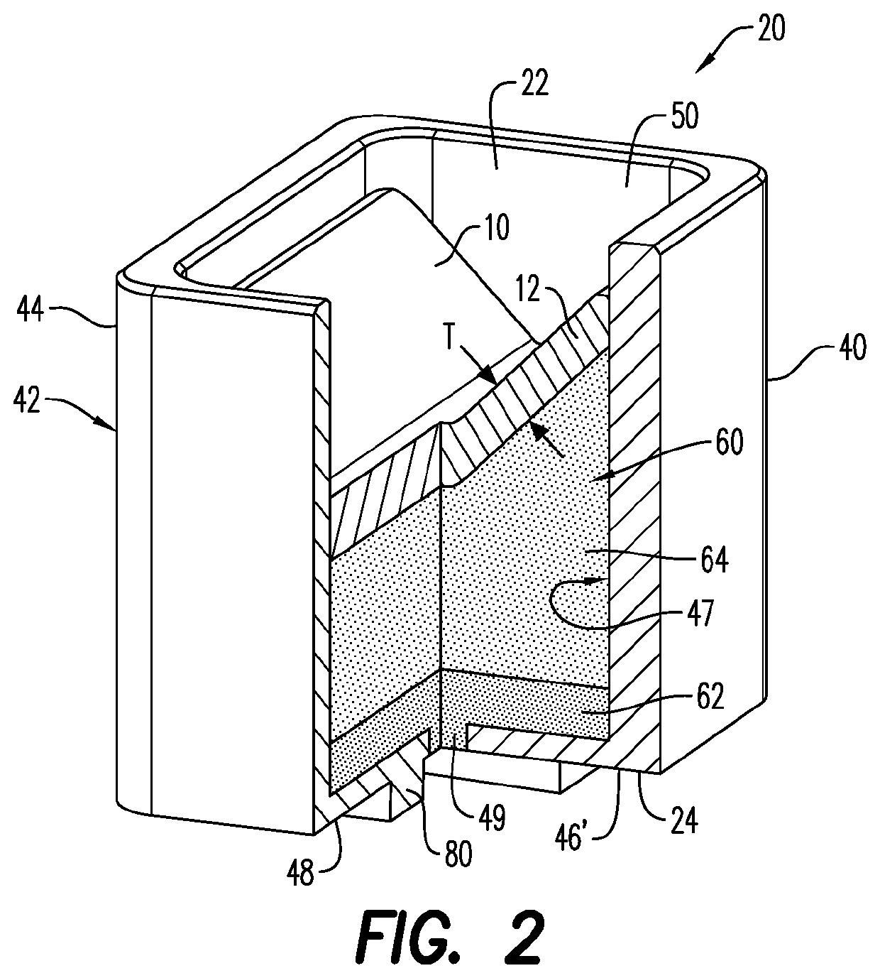
[0078]Sample shaped charges were generally configured to demonstrate the performance of shaped charges incorporating liners made according to embodiments described herein. Each shaped charge included a case / casing, and an initiation point formed in the back wall of the case. An explosive load was arranged within the hollow interior, and liners of different compositions and grain size s of powders were positioned adjacent the explosive load. A detonating cord was positioned adjacent the initiation point. The shaped charges were detonated, measurements of the entrance hole diameters and lengths of the perforation jets were taken, and productivity ratio evaluations were made. The values presented in Table 2 represent the results of the measurements taken and evaluations made upon detonation of the shaped charges.

[0079]Two sets of commercially available (or established liners) were utilized in samples B, D and E, the liners each including various powders. Samples A, and C, however, each...


PUM

PropertyMeasurementUnit
grain sizeaaaaaaaaaa
densityaaaaaaaaaa

Abstract

A shaped charge liner including a composition of metal powders. Each metal powder may include one or more grain sizes, which may be different from other powder grain sizes. The metal powders may include transition metal powders, non-transition metal powders, and a bronze metal powder. The metal powders may include a malleable binding metal powder, such as bronze, and a non-malleable binding metal powder. A shaped charge including such liners is also disclosed, as well as a method of making the shaped charge liner, and a shaped charge including such shaped charge liner.

Description

CROSS-REFERENCE TO RELATED APPLICATIONS[0001]This application claims the benefit of U.S. Provisional Application No. 62 / 523,991, filed Jun. 23, 2017, which is incorporated herein by reference in its entirety.FIELD[0002]A shaped charge liner formed from a composition of powders is generally described. More specifically, a shaped charge having a shaped charge liner including a composition of metal powders is described.BACKGROUND[0003]As part of a well completion process, cased-holes / wellbores are perforated to allow fluid or gas from rock formations (reservoir zones) to flow into the wellbore. Perforating gun string assemblies are conveyed into vertical, deviated or horizontal wellbores, which may include cemented-in casing pipes and other tubulars, by slickline, wireline or tubing conveyance perforating (TCP) mechanisms, and the perforating guns are fired to create openings / perforations in the casings and / or liners, as well as in surrounding formation zones. Such formation zones may ...

Claims


Application Information

Patent Timeline
Patent Type & Authority Patents(United States)
IPC IPC(8): F42B1/032B22F1/00E21B43/117F42B1/036F42B1/028B22F1/05
CPCE21B43/117F42B1/032B22F1/0011F42B1/036B22F2301/30B22F2301/052F42B1/028B22F2304/10B22F2301/10B22F2301/15B22F1/05
Inventor LOEHKEN, JOERN OLAFMONTENEGRO, FRANCISCO
Owner DYNAENERGETICS EURO GMBH
Why Eureka
Try Eureka