Screw less cover plate for electrical fixtures

a technology for electrical fixtures and cover plates, applied in the direction of electrical equipment, electrical wiring components, receptacle boxes, etc., can solve the problems of a lot of fixing problems and problems, and achieve the effects of reducing manufacturing and packaging costs, saving time, labor and expense, and facilitating installation

Active Publication Date: 2020-08-11
DJW DEV LLC
View PDF8 Cites 0 Cited by
  • Summary
  • Abstract
  • Description
  • Claims
  • Application Information

AI Technical Summary

Benefits of technology

[0014]Advantageously, the screw less cover plate provides easy installation, without the use of tools, and sustained coverage of an electrical box without the need for or use of screws, including those used in known devices through holes in the cover plate or in a separate device that intervenes between the electrical box and the cover plate. The latter devices appear to be screw less on the face of the cover plate, but actually use screws on the intervening device to connect the intervening device to the electrical device. A rear side of the screw less cover plate has two prongs attached as an integral part of the cover plate. The prongs extend rearward from the cover plate and are orthogonal to a face of the cover plate. The prongs are positioned in such a manner that they align with threaded holes in the electrical switch conventionally used to receive screws for fastening the cover plate to the switch. The technology disclosed herein uses no such intervening device. Additionally, utilizing a cover plate without screws ensures that no mismatch between screws and the cover plate exists.
[0015]Further advantageously, the screw less cover plate provides a solution in which time, labor, and expenses are saved due to the ease of use and installation without screws and tools. Manufacturing and packaging costs are also lessened due to the elimination of the screws and elimination of any intervening devices. Use of the screw less cover plate also saves the environment with its use of fewer parts, less packaging, and the elimination of painting of the screws.

Problems solved by technology

But this leads to a lot of fixing issues and problems as the dimensions of the screws are not aligned with the cover plate dimensions so that the cover plate is tightly and safely secured with the electrical device by getting it inserted into the electrical component of the electrical device.

Method used


Image

  • Screw less cover plate for electrical fixtures
  • Screw less cover plate for electrical fixtures
  • Screw less cover plate for electrical fixtures

Examples


Embodiment Construction

[0052]Before describing the disclosed embodiments of this technology in detail, it is to be understood that the technology is not limited in its application to the details of the particular arrangements shown here since the technology described is capable of other embodiments. Also, the terminology used herein is for the purpose of description and not of limitation.

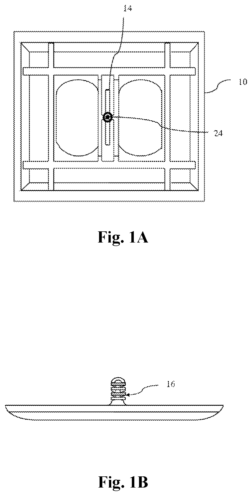
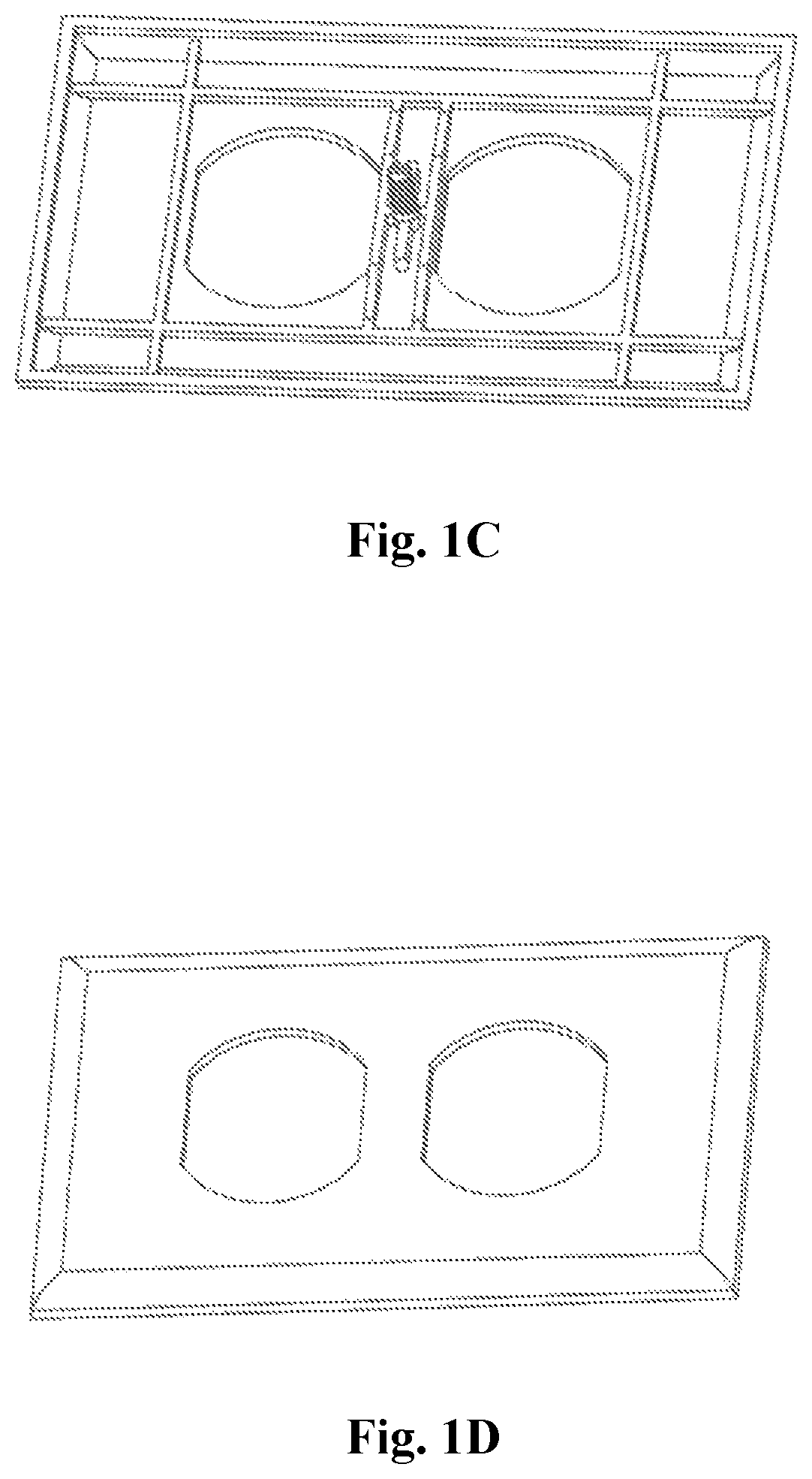
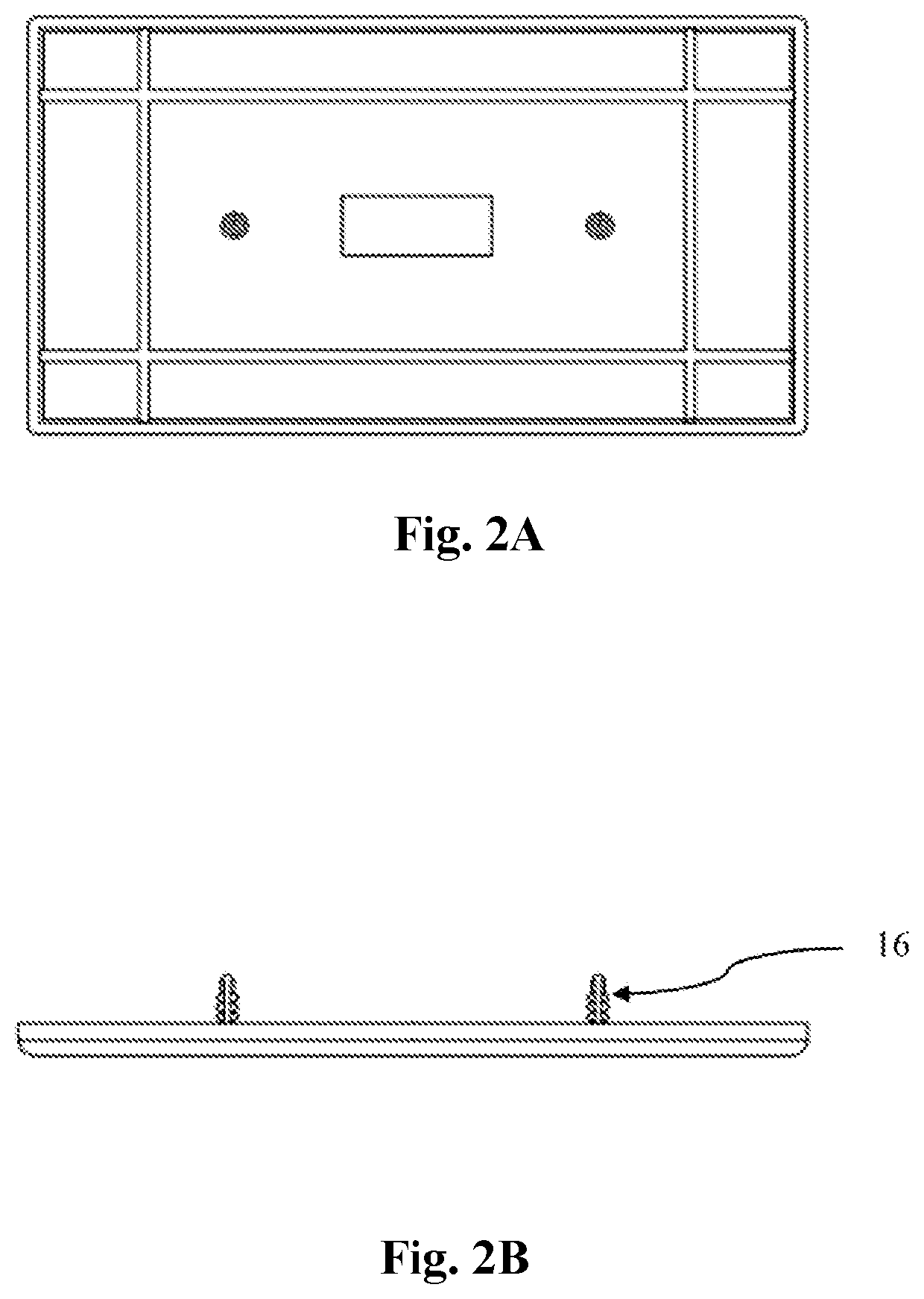
[0053]In various exemplary embodiments, the technology described herein provides a one-piece screw less cover plate to attach any electrical device to cover a receptacle box, such as, for example but not limited to, an electrical receptacle box for an electrical outlet.

[0054]Reference will now be made in detail to the description of the present subject matter, one or more examples of which are shown in figures. Each example is provided to explain the subject matter and not a limitation. Various changes and modifications obvious to one skilled in the art to which the invention pertains are deemed to be within the spirit, s...


PUM


Abstract

A screw less, adjustable cover plate for electrical fixtures is disclosed. The cover plate has a rear side which comprises of a prong attached thereto or molded as an integral part of the cover plate. The prong extends rearward from the cover plate and is orthogonal to a face of the cover plate. The prong is positioned in such a manner that it aligns with a threaded hole in the electrical outlet conventionally used to receive a screw for fastening the cover plate to the outlet. In an embodiment, the prong is configured to be pushed and not threaded into the threaded hole, in order to secure the cover plate to the electrical outlet. In this manner, the cover plate can be quickly installed without any tools and screws.

Description

TECHNICAL FIELD OF THE INVENTION[0001]The technology described herein relates generally to electrical wiring components, electrical devices, receptacle boxes, cover plates, and cover plate assemblies. More specifically, this technology relates to a screw less cover plate for electrical device fixtures.BACKGROUND OF THE INVENTION[0002]The purpose of a cover plate is to provide a decorative cover for the receptacle box installation while also preventing operator exposure to the interior of the receptacle box, which in many instances contains electrical wiring. By way of example, a cover plate can cover a receptacle box containing devices such as ON / OFF switches, outlet receptacles, dimmers, motor speed selector switches, coaxial cable connectors, TV antenna connectors, telephone jacks, computer network cable connectors, informational devices such as clocks, thermometers, security systems, and so forth.[0003]Known cover plates are typically constructed in the form of a generally flat p...

Claims


Application Information

Patent Timeline
Patent Type & Authority Patents(United States)
IPC IPC(8): H02G3/14
CPCH02G3/14
Inventor WAYNICK, DOVELYN JPROBASCO, MAX
Owner DJW DEV LLC
Why Eureka
Try Eureka