Vibration testing system and methodology

a vibration testing and vibration technology, applied in vibration testing, measuring devices, instruments, etc., can solve the problems of affecting the the corresponding decrease of the remaining service life of the vibration testing apparatus, and the dramatic increase of the wear and tear of the shaker, so as to prevent unexpected wear and tear induced failures, improve production planning, and eliminate unnecessary and wasteful service or maintenance activities

Active Publication Date: 2020-08-18
BRUEL & KJAER VTS
View PDF24 Cites 3 Cited by
  • Summary
  • Abstract
  • Description
  • Claims
  • Application Information

AI Technical Summary

Benefits of technology

[0014]The display of the remaining and / or consumed service-life of the present vibration testing system provides the relevant personnel with a beneficial mechanism for assessing or evaluating accurately when service will be due. The availability of this service-life information is capable of improving production planning by preventing unexpected wear and tear induced failures of the vibration testing apparatus in-between planned service intervals. The display of the service-life information is also able to eliminate unnecessary and wasteful service or maintenance activities on the vibration testing apparatus in situations where shaker loading, and hence the number of armature force cycles, has been smaller than expected at the time when the service interval was planned.

Problems solved by technology

The moving elements of the vibration testing apparatus such as an armature coil, and its frame and bearings, and rollers (guidance system) are subject to wear, tear and fatigue as the electrodynamic shaker is operated.
However, the amount of wear and tear is strongly dependent on the force produced by the payload on the electrodynamic shaker such that even a small increase of payload leads to a dramatic increase of the wear and tear of the shaker and a corresponding decrease of the remaining service life of the vibration testing apparatus.
The regime of reactive observation means that malfunctions or errors of the vibration testing system that occur in-between the planned service intervals have only been detected and reported by the operator or user when obvious errors such as audible, tactile or visible anomalies in the function of the electrodynamic shaker are noticeable.
The fixed or pre-programmed service intervals lead to several problems for an optimal use and exploitation of existing vibration testing apparatuses and systems.
One of these problems is a changing usage pattern of the vibration test apparatuses which deviates from the usage pattern employed to determine the length of the service interval.
Because the amount of wear and tear on movable components of the vibration test apparatuses, in particular the electrodynamic shaker, depend so strongly on the armature force these types of deviation from the expected usage pattern can on one hand lead to a much shorter service life than expected and therefore failure of the vibration testing apparatuses in-between the service intervals during use.
On the other hand, if the shaker loading and accompanying armature force is smaller than expected, the time between the planned service intervals will be unnecessarily short and waste user resources and costs in connection with the operation of the vibration testing system and apparatus

Method used


Image

  • Vibration testing system and methodology
  • Vibration testing system and methodology

Examples


Embodiment Construction

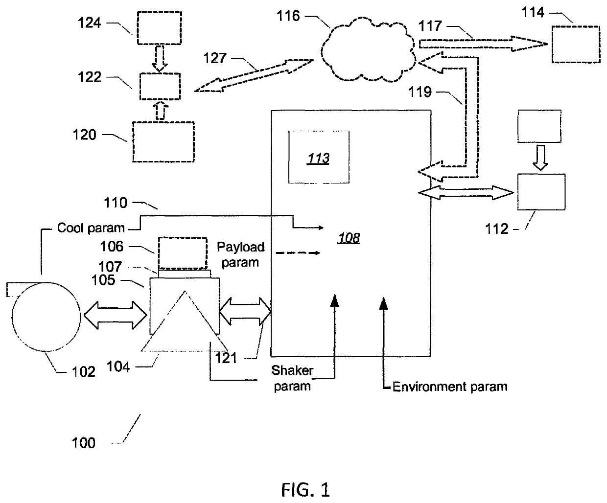
[0041]FIG. 1 shows a simplified schematic drawing of a vibration testing apparatus forming part of a vibration testing system 100 in accordance with a first embodiment of the invention. The vibration testing apparatus comprises a power amplifier 108, mounted in a separate housing or casing, operatively coupled to an electrodynamic shaker 104 via a signal and power cable 121. The electrodynamic shaker 104 comprises a vibrateable armature 105 mechanically coupled to a payload support structure 107. The latter holds a payload 106 which is the equipment or component under vibratory test. The vibration testing apparatus comprises a display 113 which is mounted to a floor-standing housing or frame of the power amplifier 108 in the present embodiment of the invention. The display 113 may comprise a separate and remotely arranged display in other embodiments of the system 100 or a combination of a remote display and a display mounted on the floor-standing housing or frame of the power ampli...


PUM


Abstract

A vibration testing system (VTS) including a vibration testing apparatus, which includes a power amplifier operatively coupled to an electrodynamic shaker. The shaker includes a vibrateable armature mechanically coupled to a payload support structure. A data logger measures and records respective values of operational parameters of the shaker over time during mechanical excitation of the payload. A controller of the VTS reads and processes logged values of the operational parameters and determines an accumulated number of armature force cycles based on the recorded values of the operational parameters. The controller computes a remaining service-life or a consumed service life of the electrodynamic shaker based on the accumulated number of armature force cycles and a predetermined service-life of the vibration testing apparatus. The controller indicates on a display of the VTS the remaining service-life or the consumed service life of the vibration testing apparatus.

Description

CROSS-REFERENCE TO RELATED APPLICATIONS[0001]This application is a U.S. National Stage of International Application No. PCT / EP2015 / 056741, filed Mar. 27, 2015, which claims the benefit of European Patent Application No. 14163418.8, filed Apr. 3, 2014, both of which are incorporated herein by reference in their entireties.[0002]The present invention relates to a vibration testing system comprising a vibration testing apparatus. The vibration testing apparatus comprises a power amplifier operatively coupled to an electrodynamic shaker wherein the shaker comprises a vibrateable armature mechanically coupled to a payload support structure. A data logger is configured to measure and record respective values of one or more operational parameters of the electrodynamic shaker over time during mechanical excitation of the payload. A processor or controller of the vibration testing system is configured to read and process logged values of the one or more operational parameters and determining...

Claims


Application Information

Patent Timeline
Patent Type & Authority Patents(United States)
IPC IPC(8): G01M7/02G05B23/02
CPCG01M7/02G05B23/0283
Inventor WILLIAMSON, ALEXANDERBIDWELL, TIM
Owner BRUEL & KJAER VTS
Why Eureka
Try Eureka