
Strength training device for swingable sports equipment
a technology of swinging sports equipment and training devices, which is applied in the field of sports-related exercise equipment, can solve the problems of inability to target the desired muscle groups using traditional weight lifting apparatus, the risk of wrist or back injury, and the inability to swing weighted clubs or bars in this manner, so as to improve the strength of the athlete, avoid boredom, and minimize the effect of time-consuming
- Summary
- Abstract
- Description
- Claims
- Application Information
AI Technical Summary
Benefits of technology
Problems solved by technology
Method used
Image

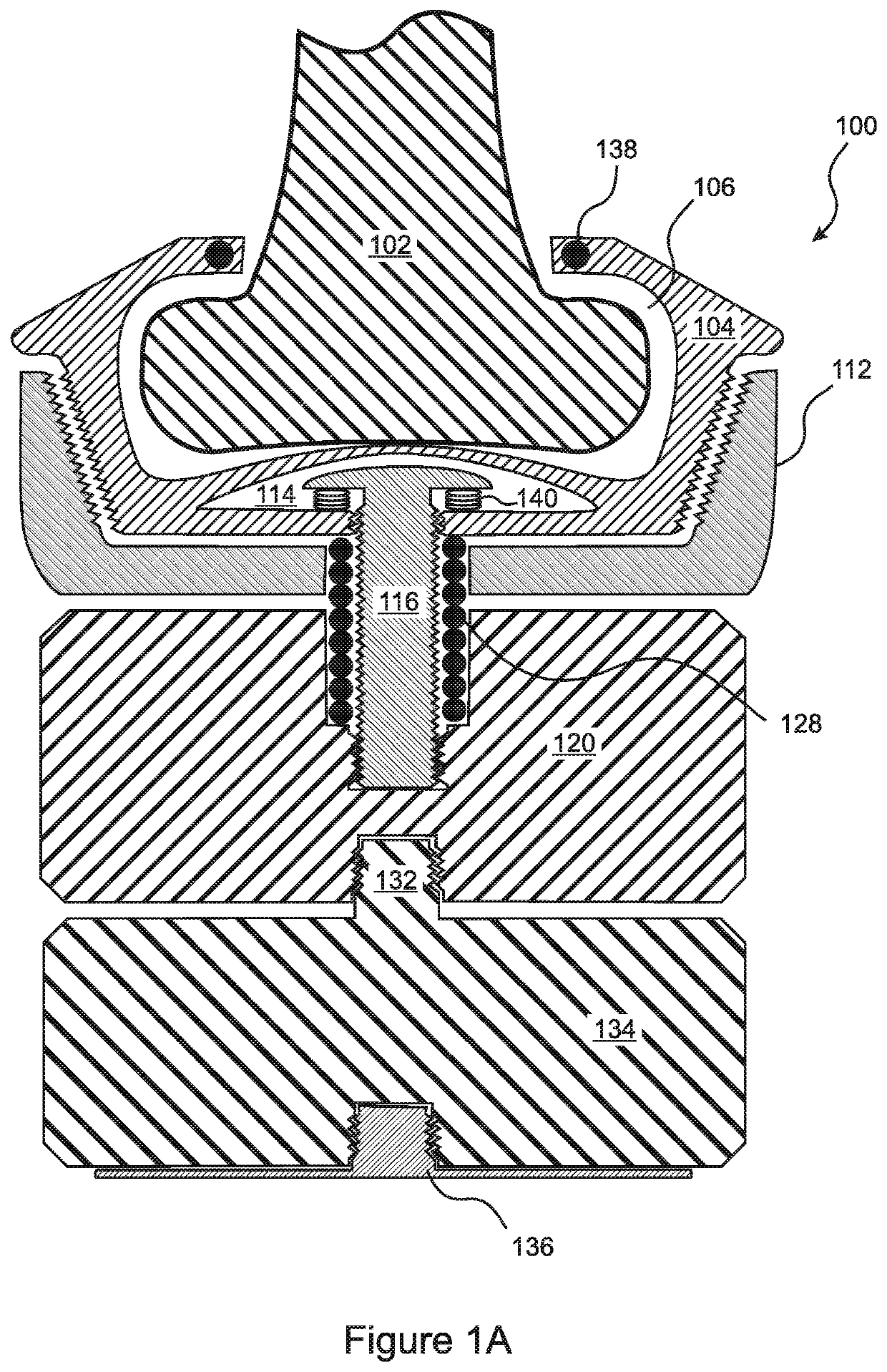
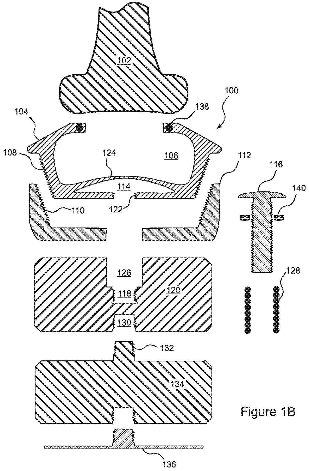
Examples
second embodiment
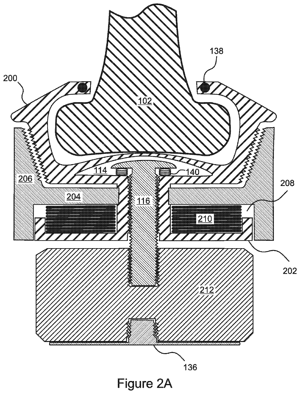
[0037]FIGS. 2A and 2B are cross-sectional illustrations of the present invention. In this embodiment, a lower structure 202 of the flexible inner component 200 extends below the bottom 204 of the rigid outer member 206, such that a chamber 208 is formed therebetween. A compression spring 210 is inserted in the chamber 208 so that it presses against the lower structure 202 of the inner component 200 and the bottom 204 of the outer component 206. Accordingly, the weight 212 in this embodiment does not include a cavity for insertion of a compression spring.
third embodiment
[0038]FIG. 3A is a perspective exploded view of the present invention. FIGS. 3B, 3C, and 3D are top, front, and side views respectively of the embodiment of FIG. 3A. This embodiment comprises a split-ring clamp 300 that includes two half-rings that are attached at both ends by clamps 302, wing nut and bolt attachment, or another attachment mechanism as is known in the art. The diameter of the clamp 300 is less than the diameter of the base of the bat 102, such that engagement of the clamping mechanism causes the clamp 300 to press firmly against the bat. One or more weights 134 are then attached to a base 304 of the clamp 300 by a threaded male extension 132.
[0039]With reference to FIG. 4, in other embodiments the “flexible component”400 is actually made from a rigid material, wherein the upper portion thereof comprises a plurality of segments 402 that are hinged 404 near a lower periphery thereof. In some of these embodiments, the bolt 406, which can be a plug (i.e. need not be thr...
PUM
 Abstract
Description
Claims
Application Information