Wire electrical discharge machine with deterioration detection function for feeder

a technology of wire electrical discharge machine and feeder, which is applied in the direction of electrical-based machining electrode, manufacturing tools, electric circuits, etc., can solve the problems of reducing the machining speed and the false result of machining, and achieve the effect of preventing the production of defective workpieces

Active Publication Date: 2020-08-25
FANUC LTD
View PDF28 Cites 0 Cited by
  • Summary
  • Abstract
  • Description
  • Claims
  • Application Information

AI Technical Summary

Benefits of technology

[0009]Accordingly, the object of the present invention is to provide a wire electrical discharge machine capable of detecting a deteriorated state of a feeder at an early stage.
[0014]According to the present invention, deterioration of a feeder can be detected to prevent production of defective workpieces.

Problems solved by technology

If the feeder 5 is deteriorated or broken, the machining gap between the wire electrode 2 and the workpiece 4 cannot be normally charged with energy, resulting in a reduction in the machining speed and a false result of machining.

Method used


Image

  • Wire electrical discharge machine with deterioration detection function for feeder
  • Wire electrical discharge machine with deterioration detection function for feeder
  • Wire electrical discharge machine with deterioration detection function for feeder

Examples


first embodiment

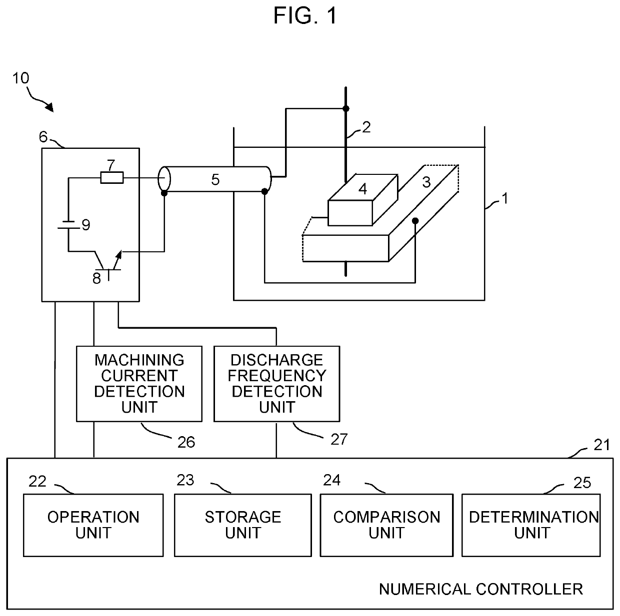
[0024]FIG. 1 is a schematic configuration diagram of a wire electrical discharge machine according to the present invention.

[0025]A wire electrical discharge machine 10 of the present embodiment is an equivalent of the prior art wire electrical discharge machine 10 shown in FIG. 7 to which a numerical controller 21, machining current detection unit 26, and discharge frequency detection unit 27 are added. The numerical controller 21 comprises an operation unit 22, storage unit 23, comparison unit 24, and determination unit 25. In the present embodiment, the numerical controller 21, machining current detection unit 26, and discharge frequency detection unit 27 constitute a feeder deterioration detection unit.

[0026]The wire electrical discharge machine 10 of the present embodiment, like the conventional one, performs electrical discharge machining by applying a voltage from a machining power supply 6 to a wire electrode 2 and a workpiece 4 on a table 3 through a feeder 5, in a machinin...

second embodiment

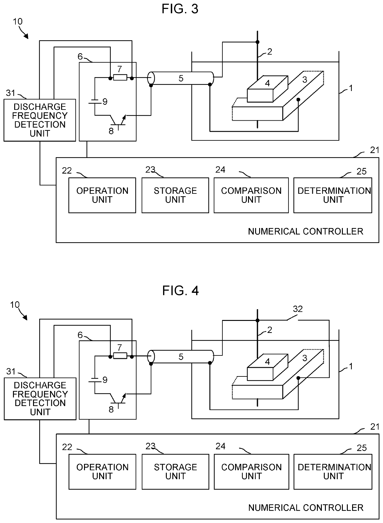
[0043]FIG. 3 is a schematic configuration diagram of a wire electrical discharge machine according to the present invention.

[0044]A wire electrical discharge machine 10 of the present embodiment is an equivalent of the prior art wire electrical discharge machine 10 shown in FIG. 7 to which a numerical controller 21 and a resistance voltage detection unit 31 are added. The numerical controller 21 comprises an operation unit 22, storage unit 23, comparison unit 24, and determination unit 25. In the present embodiment, the numerical controller 21 and the resistance voltage detection unit 31 constitute a feeder deterioration detection unit.

[0045]The wire electrical discharge machine 10 of the present embodiment, like the conventional one, performs electrical discharge machining by applying a voltage from a machining power supply 6 to a wire electrode 2 and a workpiece 4 on a table 3 through a feeder 5, in a machining tank 1. The machining power supply 6 comprises a resistive element 7, ...


PUM

PropertyMeasurementUnit
voltageaaaaaaaaaa
currentaaaaaaaaaa
machining currentaaaaaaaaaa

Abstract

A wire electrical discharge machine is configured to perform removal machining of a workpiece by applying a voltage to a machining gap between a wire electrode and the workpiece through a feeder to generate electrical discharge and is provided with a feeder deterioration detection unit configured to detect deterioration of the feeder. The feeder deterioration detection unit includes a detection unit configured to detect a machining current value during the machining and a detection unit configured to detect the number of electrical discharges during the machining.

Description

RELATED APPLICATIONS[0001]The present application claims priority to Japanese Patent Application Number 2016-001583, filed Jan. 7, 2016, the disclosure of which is hereby incorporated by reference herein in its entirety.BACKGROUND OF THE INVENTION[0002]Field of the Invention[0003]The present invention relates to a wire electrical discharge machine capable of detecting deterioration of a feeder.[0004]Description of the Related Art[0005]In a wire electrical discharge machine for wire electrical discharge machining, as described in Japanese Patent Application Laid-Open No. 2010-52092, for example, a feeder is used to apply a voltage from a machining power supply to a machining gap between a wire electrode and a workpiece to generate electrical discharge, thereby machining the workpiece.[0006]FIG. 7 is a schematic configuration diagram of a conventional wire electrical discharge machine.[0007]A wire electrical discharge machine 10 performs electrical discharge machining by applying a vo...

Claims


Application Information

Patent Timeline
Patent Type & Authority Patents(United States)
IPC IPC(8): B23H1/04B23H1/02B23H7/04B23H11/00
CPCB23H1/024B23H7/04B23H1/026B23H11/00B23H7/02B23H1/00B23H7/16B23H11/006
Inventor MATSUNAGA, TOMOAKIKAWAHARA, AKIYOSHI
Owner FANUC LTD
Why Eureka
Try Eureka