Gas detection apparatus

a technology of gas detection and detection apparatus, which is applied in the direction of measurement devices, instruments, scientific instruments, etc., can solve the problems of reducing the accuracy of detecting the concentration of the first gas component, deteriorating the gas detection section, so as to suppress the decrease of the detection accuracy

Inactive Publication Date: 2018-12-06
SPIROSURE INC +1
View PDF15 Cites 0 Cited by
  • Summary
  • Abstract
  • Description
  • Claims
  • Application Information

AI Technical Summary

Benefits of technology

[0008]It is therefore an object of the present invention to provide a gas detection apparatus which detects the concentration of a first gas component

Problems solved by technology

However, the above-described conventional gas detection apparatus has a problem in that the accuracy in detecting the concentration of the first gas component may be lowered as a result of detecting the first gas component over a long period of time.
In particular, there is a possibility that the gas detection section d

Method used


Image

  • Gas detection apparatus
  • Gas detection apparatus
  • Gas detection apparatus

Examples


first embodiment

1. First Embodiment

1-1. Overall Structure

[0042]A gas detection apparatus 1 for detecting the concentration of NOx (a first gas component) contained in exhaled air (gas under measurement G1) will be described as a first embodiment.

[0043]The gas detection apparatus 1 is used to measure NOx contained in exhaled air at a very low concentration (at a level of several ppb to several hundreds of ppb) for the purpose of, for example, diagnosis of asthma.

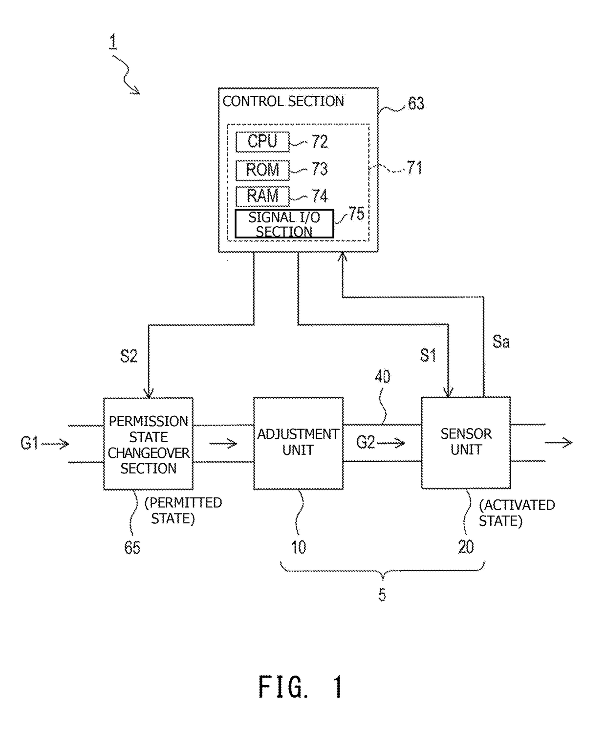
[0044]As shown in FIG. 1, the gas detection apparatus 1 includes a gas sensor 5 for measuring NOx contained in the gas under measurement G1, a control section 63 for controlling the gas sensor 5, and a permission state changeover section 65 for switching the state of supply of the gas to the gas sensor 5 (an adjustment unit 10).

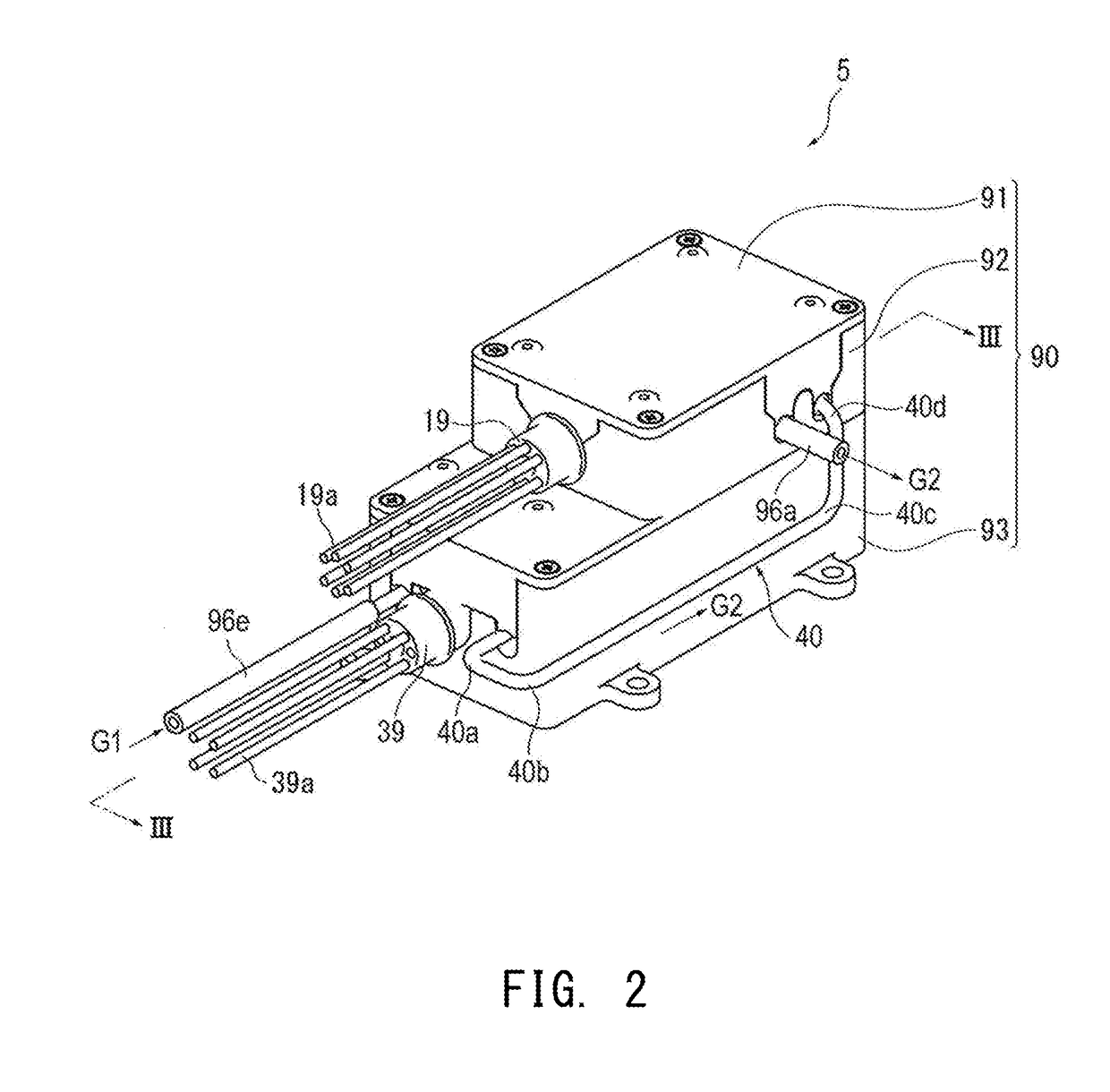
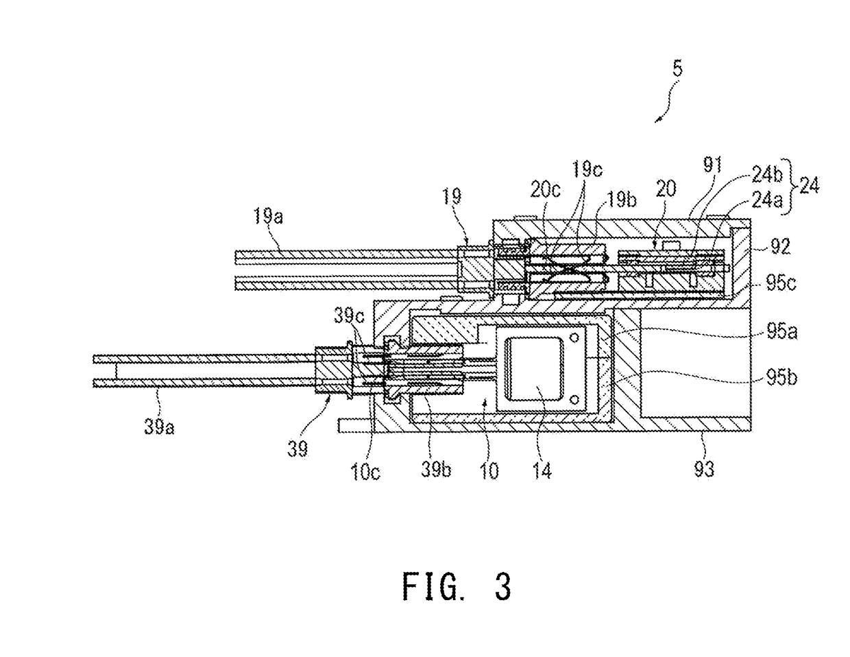
[0045]The gas sensor 5 includes the adjustment unit 10 and a sensor unit 20.

[0046]The adjustment unit 10 includes a catalyst (MCR, Micro Channel Reactor) for converting NO contained in the gas under measurement G1 sup...

second embodiment

2. Second Embodiment

2-1. Overall Configuration

[0109]A second gas detection apparatus 101 which includes a moving direction changeover section 66 in place of the permission state changeover section 65 in the gas detection apparatus1 of the first embodiment will be described as a second embodiment.

[0110]Notably, of the constituent elements of the second gas detection apparatus 101 of the second embodiment, constituent elements identical with those of the gas detection apparatus 1 of the first embodiment will be described using the same reference numerals. In the following description, a portion of the second embodiment different from the first embodiment will mainly be described.

[0111]As shown in FIG. 6, the second gas detection apparatus 101 includes the gas sensor 5 for measuring NOx contained in the gas under measurement G1 the control section 63 for controlling the gas sensor 5, and the moving direction changeover section 66 for switching the moving direction of gas supplied to th...

third embodiment

3. Third Embodiment

3-1. Overall Configuration

[0135]A third gas detection apparatus 201 including a flow channel changeover section 85 which switches a supply source flow channel for the gas supplied to the sensor unit 20 will be described as a third embodiment.

[0136]Notably, of the constituent elements of the third gas detection apparatus 201 of the third embodiment, constituent elements identical with those of the gas detection apparatus 1 of the first embodiment will be described using the same reference numerals. In the following description, a portion of the third embodiment different from the first embodiment will be mainly described.

[0137]As shown in FIG. 8, the third gas detection apparatus 201 includes the gas sensor 5 for measuring NOx contained in the gas under measurement G1, the control section 63 for controlling the gas sensor 5, and the flow channel changeover section 85 which switches the supply source flow channel for the gas supplied to the sensor unit 20 of the gas...


PUM


Abstract

A gas detection apparatus for detecting the concentration of a first gas component contained in a gas under measurement includes a gas conversion section for convening the first gas component to a second gas component, a gas detection section whose electrical characteristics change with a change in the concentration of the second gas component when the gas detection section is in an activated state, and a detection state setting section. During a detection period, the detection state setting section sets the state of gas detection by the gas detection section to a detection executed state in which the gas detection section can detect the second gas component. During periods which are not the detection period, the detection state setting section sets the state of gas detection by the gas detection section to a detection suspended state in which the gas detection section does not detect the second gas component.

Description

BACKGROUND OF THE INVENTION1. Field of the Invention[0001]The present invention relates to a gas detection apparatus.2. Description of the Related Art[0002]Gas detection apparatuses for detecting the concentration of a first gas component contained in a gas under measurement are known (see, for example, Japanese Patent Application Laid-Open (kokai) No. H10-300702).[0003]Some such gas detection apparatuses include a gas conversion section and a gas detection section. The gas conversion section converts at least a portion of the first gas component contained in the gas under measurement to a second gas component such that the ratio between the partial pressures of the first gas component and the second gas component coincides with that in the equilibrium state. A converted gas produced as a result of conversion at the gas conversion section is supplied to the gas detection section, and the gas detection section is brought into an activated state in which the gas detection section can ...

Claims


Application Information

Patent Timeline
IPC IPC(8): G01N27/12G01N33/00
CPCG01N27/125G01N33/0013G01N33/0037Y02A50/20
Inventor MORITA, KAZUTONISHIYAMA, HIROYUKIYOKOYAMA, TAKAHIROTAKAKURA, MASAHIROITO, TATSUNORIUSHIDA, TAKAHISASSENYANGE, SOLOMONAWABDY, BRIANLEARD, RYAN RICHARD
Owner SPIROSURE INC
Why Eureka
Try Eureka