
Unmanned underwater vehicle and method for controlling hydraulic system

a technology of hydraulic system and underwater vehicle, which is applied in underwater equipment, special-purpose vessels, transportation and packaging, etc., can solve the problems of affecting the operation of hydraulic circuit at relatively high temperature conditions, fluid may become thick and difficult to move through the hydraulic circuit, and affect the efficiency of hydraulic operation, so as to prevent deterioration of the efficiency of the tools, maintain the effect of circulation and temperature increas

Active Publication Date: 2020-09-01
FUGRO NV
View PDF6 Cites 0 Cited by
  • Summary
  • Abstract
  • Description
  • Claims
  • Application Information

AI Technical Summary

Benefits of technology

The patent is about controlling the flow of hydraulic fluid in a system using valves that are controlled based on temperature. This allows for efficient activation or deactivation of tools, prevention of cooling of stagnant fluid, and maintaining temperature without the need for additional heating systems. Additionally, the patent describes controlling a short-circuit path of hydraulic fluid to prevent uncontrolled activation of tools, while still maintaining efficient circulation. The valve system used in the patent is configured to maintain at least 50% of the hydraulic fluid flow even when no tools are actuated, which allows for the use of higher viscosity oil in the system.

Problems solved by technology

However, when operating in deep water conditions, the hydraulic fluid may be affected by cold surroundings and / or high pressure of the water.
In particular, when the hydraulic fluid cools down, the fluid may become thick and difficult to move through the hydraulic circuit, especially if the fluid has become stagnant when a tool is not used for some time.
However, using low viscosity oil may affect operation at relatively high temperature conditions.
However, the heating mechanisms available underwater such as, e.g., electrical heating under water may consume too much power and could present failures, such as short circuits.
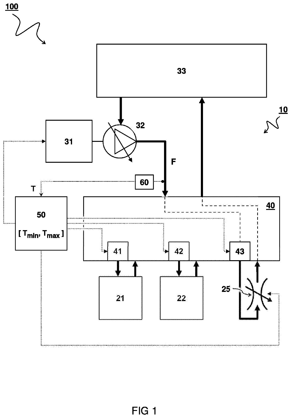
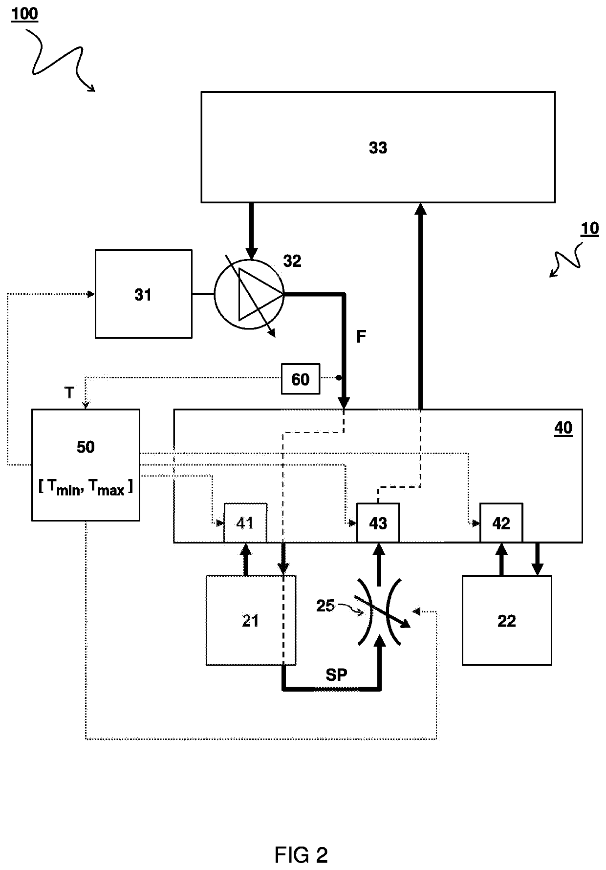
In this manner, the circulation of hydraulic fluid may in itself result in heating of the fluid, e.g. by friction and / or pump action.

Method used


Image

  • Unmanned underwater vehicle and method for controlling hydraulic system
  • Unmanned underwater vehicle and method for controlling hydraulic system

Examples


Embodiment Construction

[0020]In some instances, detailed descriptions of well-known devices and methods may be omitted so as not to obscure the description of the present systems and methods. Terminology used for describing particular embodiments is not intended to be limiting of the invention. As used herein, the singular forms “a”, “an” and “the” are intended to include the plural forms as well, unless the context clearly indicates otherwise. The term “and / or” includes any and all combinations of one or more of the associated listed items. It will be understood that the terms “comprises” and / or “comprising” specify the presence of stated features but do not preclude the presence or addition of one or more other features. It will be further understood that when a particular step of a method is referred to as subsequent to another step, it can directly follow said other step or one or more intermediate steps may be carried out before carrying out the particular step, unless specified otherwise. Likewise i...


PUM


Abstract

An unmanned underwater vehicle (UUV) with a hydraulic system (100) for use in cold surroundings and method of controlling such hydraulic system. The hydraulic system (100) comprises a hydraulic circuit (10). One or more tools (21,22) may be hydraulically operable via the hydraulic circuit (10). A pump (32) is configured to pressurize a flow of hydraulic fluid (F) via the hydraulic circuit (10) e.g. for actuating the tools (21,22). A valve system (40) comprises control valves (41,42,43) disposed in the hydraulic circuit (10) for controlling the flow of hydraulic fluid (F) through the hydraulic circuit (10). A controller (50) is configured to control one or more of the control valves (43) as a function of a temperature (T) of the hydraulic fluid (F).

Description

CROSS-REFERENCE TO RELATED APPLICATIONS[0001]This application is a national stage application of International Application No. PCT / NL2017 / 050438, which was filed on Jul. 3, 2017, which claims priority to Netherlands Application Number 2017106 filed on Jul. 5, 2016, of which is incorporated by reference in its entirety.TECHNICAL FIELD AND BACKGROUND[0002]The present disclosure relates to an unmanned underwater vehicle for deep water conditions. The disclosure also relates to a method of controlling a hydraulic system in such a vehicle.[0003]A hydraulic system uses a pressurized hydraulic fluid, e.g. oil, to power hydraulic tools. The hydraulic system typically comprises a hydraulic pump driven by a motor to pressurize the hydraulic fluid. The pressurized fluid is guided via a hydraulic circuit to the tools. The hydraulic circuit may comprise valves, filters, piping etcetera to guide and control the system. A hydraulic tool may comprise an actuator such as a hydraulic motor or cylinde...

Claims


Application Information

Patent Timeline
Patent Type & Authority Patents(United States)
IPC IPC(8): B63C11/52B63G8/00F15B21/042
CPCB63G8/001B63G8/00F15B21/042B63C11/52F15B2211/611B63G2008/002F15B2211/40515F15B2211/6343F15B2211/41563F15B2211/426F15B2211/62F15B2211/665F15B21/0427
Inventor ASH, BENJAMIN JEREMYANDERSON, ALAN NEILL
Owner FUGRO NV
Learn More