Lighting device

a technology of lighting device and light source, which is applied in the direction of protective devices for lighting, lighting and heating apparatus, semiconductor devices for light sources, etc., can solve the problems of cumbersome handling of the plurality of flexibly connected parts, requiring extensive cabling efforts, etc., and achieves a smaller cross section width. , the effect of convenient operation

Active Publication Date: 2020-09-15
TRIDONIC
View PDF8 Cites 0 Cited by
  • Summary
  • Abstract
  • Description
  • Claims
  • Application Information

AI Technical Summary

Benefits of technology

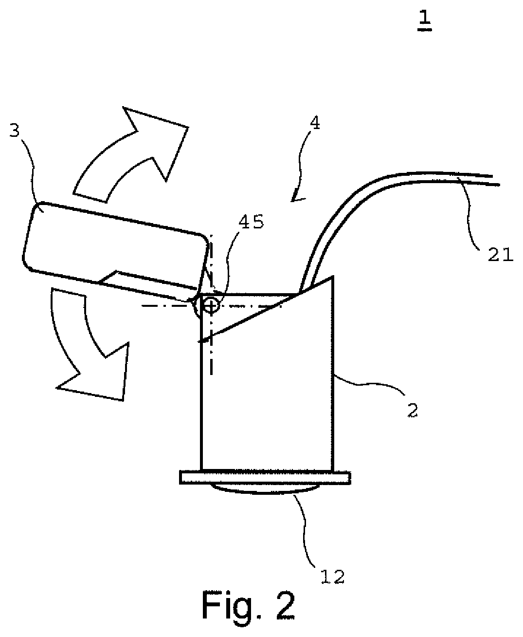
[0013]The interconnecting means of this preferred embodiment is adapted to integrally provide elastic mechanical connection between the first and second housing and simultaneously an electrical connection between charging means and electrical storage means. Thus, a single element provides electric as well as mechanic functions for the emergency lighting device, thereby reducing number of structural elements with advantageous effects for manufacturing and assembly. The elasticity of the interconnection means is chosen such that the combination of the first housing and the second housing can be handled as one device. Thus, the second housing accommodating the accumulator can easily be introduced into a recess of a detached ceiling by manipulating the first housing only. After being inserted the elasticity allows that the relative position of the first and second housing with respect to each other changes. This allows to use small gaps between the solid ceiling and the detached ceiling.
[0014]Preferably, the lighting device includes the interconnecting means comprising a cable which is over-moulded to provide compressive strength in an axial direction of the cable which at the same time providing elasticity in a traverse direction.
[0015]The interconnecting means is adapted to mechanically connect first and second housings and is itself elastic. The interconnecting means being elastic means that it is suited to transmit compressive force contrary to a flexible cable of prior art which only transmits tensile force. Hence, the mounting of the lighting means into the space behind a detached ceiling through a small opening in the detached ceiling is easier to perform than in case of the known separate functional units only linked via flexible cables.
[0016]The interconnection means being advantageously formed via encapsulating an electric connecting cable, for example injection moulding, extrusion coating, or else, provides an interconnection means combining elasticity with the necessary electrical connectivity at comparative manufacturing costs in particular as standard cables can be used. The lighting device is accordingly well adapted to being manufactured in large numbers.
[0017]The emergency lighting device according to an advantageous embodiment has the interconnecting means showing a cross section with a first width (thickness) in the first direction being smaller than a second width in a second direction orthogonal to the first direction. Both dimensions are small compared to the longitudinal extension of the connecting means.
[0018]Designing the cross section in this manner, for example with an approximately rectangular cross section, ensures a bending of the interconnection means in a preferential direction, the preferential direction given by the direction with the smaller width of the cross section.

Problems solved by technology

The remotely operated lighting controller provides a solution for the confined spaces behind wall panels, but requires extensive cabling efforts, assembling of plugs to cables and relies on gravitational force during wall mounting.
The handling of the plurality of flexibly connected parts is cumbersome.

Method used


Image

  • Lighting device
  • Lighting device
  • Lighting device

Examples


Embodiment Construction

[0048]Throughout the attached figures, same reference numerals denote the same elements. In the description of different figures, the description of elements denoted by the same reference signs is not necessarily repeated for sake of conciseness.

[0049]In the following description of embodiments an emergency lighting device 1 as an example is discussed. The invention is, nevertheless not restricted to an emergency lighting device 1, but may be applied to any lighting device including an energy storage means.

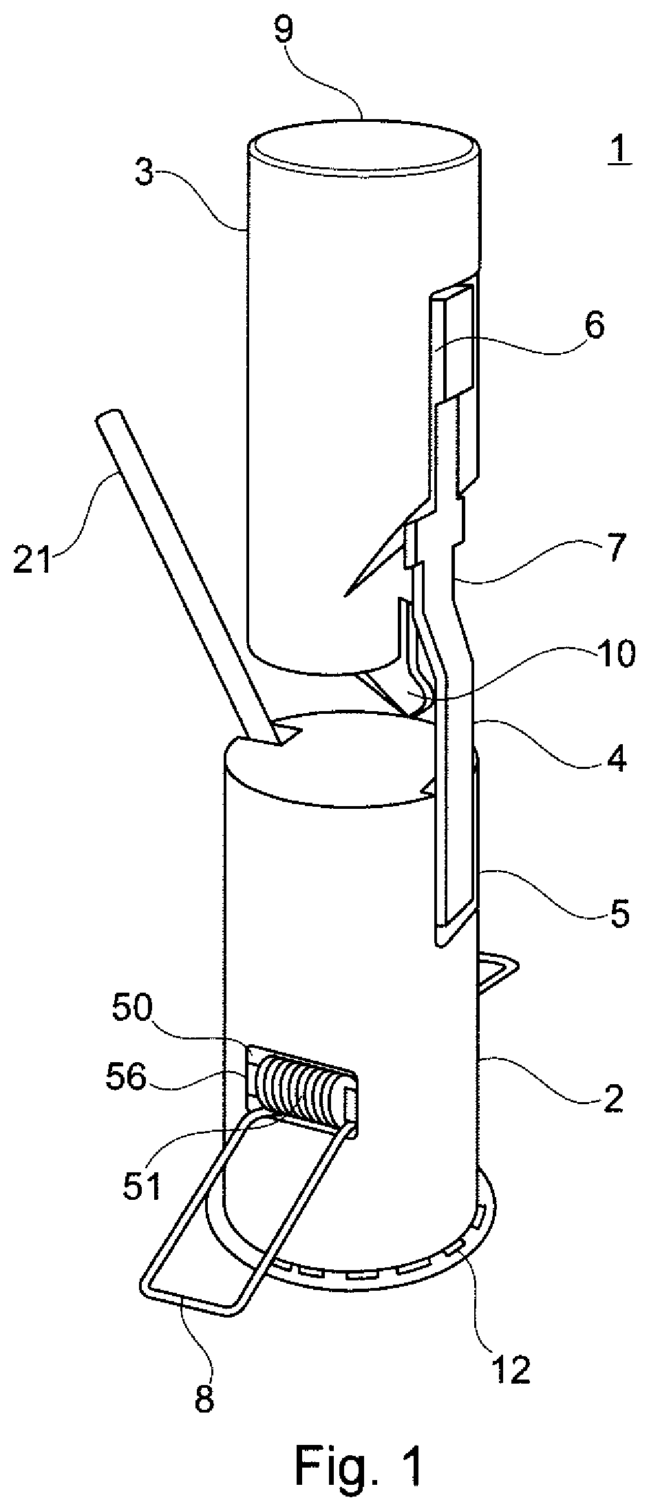
[0050]FIG. 1 shows a perspective view of an assembled emergency lighting device 1 of a preferred embodiment.

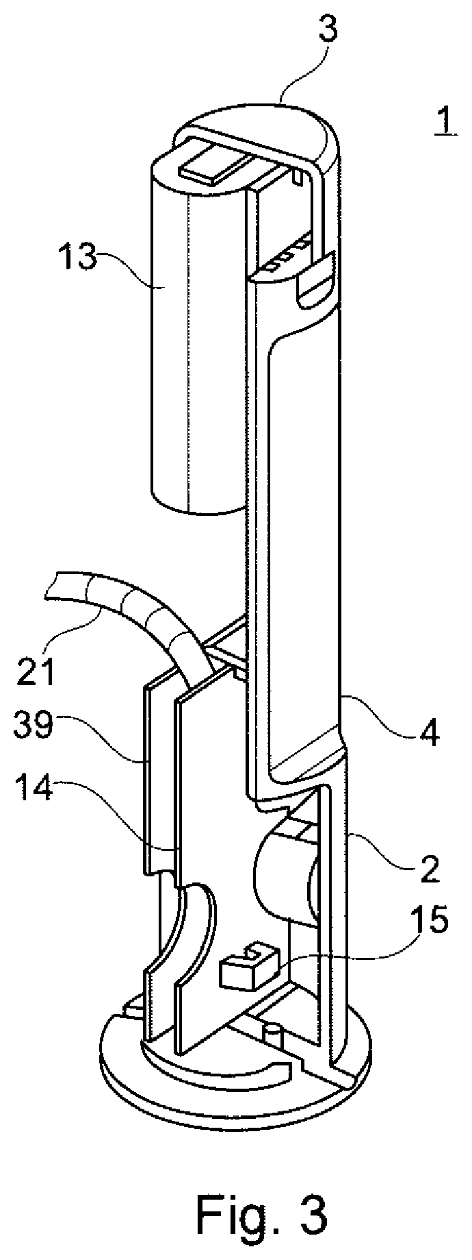
[0051]The emergency lighting device 1 comprises a first housing 2 and a second housing 3 which are detachably connected to each other by an interconnecting means 4. The interconnecting means 4 connects the first housing 2 and the second housing 3 in spaced apart manner, so that between the first housing 2 and the second housing 3 are predetermined distance is ensured.

[0052]T...


PUM


Abstract

The invention proposes a lighting device, in particular an emergency lighting device. The lighting device includes a first housing (2), a lighting means (12), for example an LED arranged at the first housing (2) and an electronic circuitry accommodated in the first housing (2) for operating the lighting means (12). A second housing (3) of the lighting device accommodates an energy storage means (13) such as a rechargeable battery, wherein the first housing (2) and the second housing (3) are arranged spaced apart. An interconnecting means (4) mechanically connects the first housing (2) and the second housing (3) in an elastic manner and also connects electrically the electronic circuitry and the energy storage means (13). The interconnecting means (4) of the lighting device of a preferred embodiment comprises a cable which is overmoulded to provide compressive strength in an axial direction of the cable.

Description

CROSS REFERENCE TO RELATED APPLICATIONS[0001]The present application is the U.S. national stage application of International Application PCT / EP2017 / 074484 filed Sep. 27, 2017, which International Application was published on May 3, 2018 as WO 2018 / 077560 A1. The International Application claims priority to European Application 16196198.2 filed Oct. 28, 2016 and Great Britain Application 1706154.0 filed Apr. 13, 2017.FIELD OF THE INVENTION[0002]The invention is in the field of luminaires and in particular in the field of emergency lighting devices. A lighting device housing arrangement, in particular for an emergency lighting device using an external power supply and including additional internal energy storage and particularly suited for arranging in confined spaces, for example for mounting in detached ceilings, is proposed.BACKGROUND OF THE INVENTION[0003]Lighting devices in the form of recessed luminaires, for example for mounting in false (detached) ceilings are widely used. App...

Claims


Application Information

Patent Timeline
Patent Type & Authority Patents(United States)
IPC IPC(8): F21S9/02F21V23/02F21V21/04F21V23/00F21V17/16F21V15/01F21S8/02F21Y115/10
CPCF21V23/001F21V15/01F21V21/046F21V23/023F21S9/022F21S8/026F21V17/164F21Y2115/10F21V23/002F21V17/107F21V23/004F21V23/06F21V17/16F21V27/00F21S9/02
Inventor DALBY, PAULJONES, GRAEMEKEARS, JOHNPARKES, STEPHENWILSON, IANRICHARDSON, JOHN
Owner TRIDONIC
Why Eureka
Try Eureka