
High-contact density electrode and fabrication technique for an implantable cuff design

a high-contact density, electrode technology, applied in the field of monitoring electrical signals, can solve the problems of not being sufficiently robust, unable to provide amputees with the intuitive control and functionality of a natural limb, and unable to use intuitive control signals that would allow amputees to take advantage of a dexterous prosthetic limb. to achieve the effect of reducing the for

Active Publication Date: 2020-09-22
CASE WESTERN RESERVE UNIV
View PDF29 Cites 0 Cited by
  • Summary
  • Abstract
  • Description
  • Claims
  • Application Information

AI Technical Summary

Benefits of technology

The patent text is describing a need for a way to monitor electrical activity in a nerve without damaging it. The invention aims to be able to identify specific signals from different parts of the nerve and to do so in a durable and gentle way.

Problems solved by technology

Despite great advances in many areas of medical technology, the challenge of providing amputees with a prosthetic limb having the intuitive control and functionality of a natural limb remains.
While such techniques may hold future promise they have, thus far, not proven to be sufficiently robust and lack the use of intuitive control signals that would allow the amputee to take advantage of a dexterous prosthetic.
But since so many bodily control signals are transmitted by the brain it is difficult to isolate the signals intended to control a prosthetic from others that are intended control another of the amputee's remaining limbs.
Such an interface is invasive, exposing the affected nerve fibers to damage from the surgical procedure to insert the protrusions.
Further damage to the nerve is also possible due to the tethering forces required necessarily exerted on the nerve to support a large number of wires corresponding to the number of individual protrusions.

Method used


Image

  • High-contact density electrode and fabrication technique for an implantable cuff design
  • High-contact density electrode and fabrication technique for an implantable cuff design
  • High-contact density electrode and fabrication technique for an implantable cuff design

Examples


Embodiment Construction

[0023]Certain terminology is used herein for convenience only and is not to be taken as a limitation on the present invention. Relative language used herein is best understood with reference to the drawings, in which like numerals are used to identify like or similar items. Further, in the drawings, certain features may be shown in somewhat schematic form.

[0024]It is also to be noted that the phrase “at least one of”, if used herein, followed by a plurality of members herein means one of the members, or a combination of more than one of the members. For example, the phrase “at least one of a first widget and a second widget” means in the present application: the first widget, the second widget, or the first widget and the second widget. Likewise, “at least one of a first widget, a second widget and a third widget” means in the present application: the first widget, the second widget, the third widget, the first widget and the second widget, the first widget and the third widget, the...


PUM


Abstract

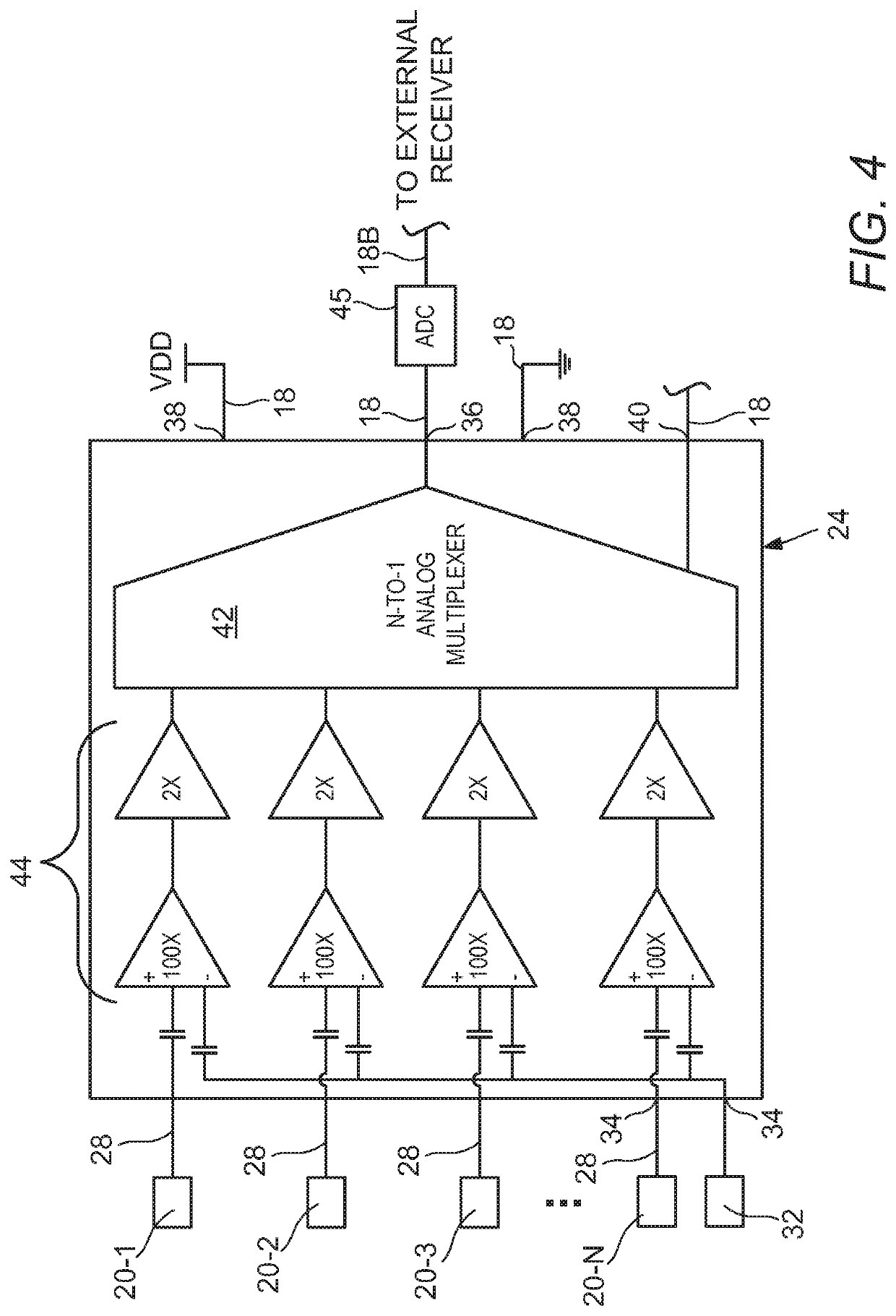
A method and an electrode for monitoring electrical activity in a nerve are provided along with a method of fabricating such an electrode. The electrode includes a cuff formed from a chronically-implantable material that, when implanted, extends at least partially around an external periphery of the nerve. A plurality of contacts are supported by the cuff to be arranged adjacent to different regions of the nerve distributed along a transverse direction of the nerve when the cuff is implanted. A multiplexer is coupled to the cuff to be implanted for receiving electrical signals introduced to the contacts by the nerve and multiplexing, in vivo, the electrical signals to be transmitted to an external receiver over a shared communication channel.

Description

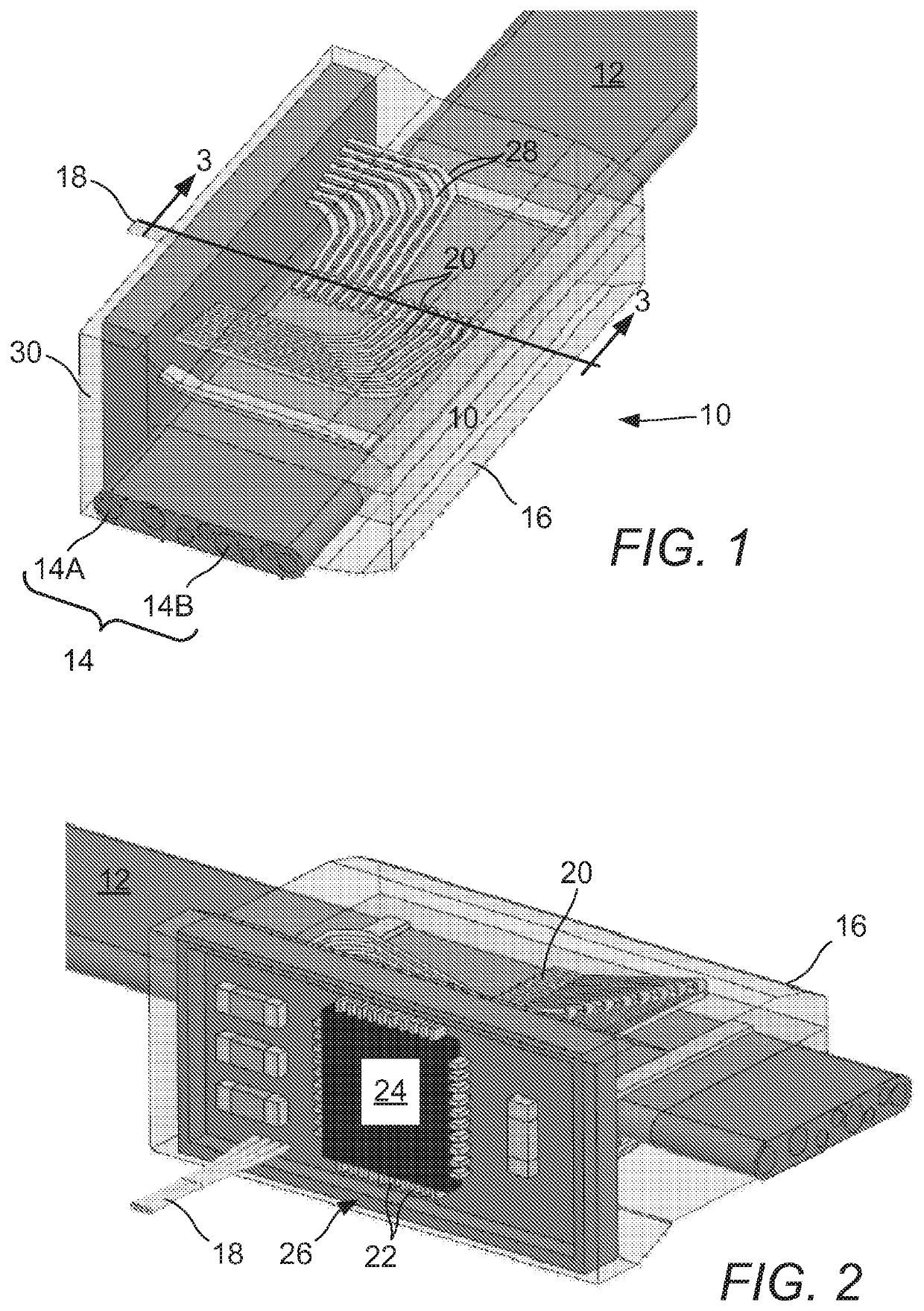
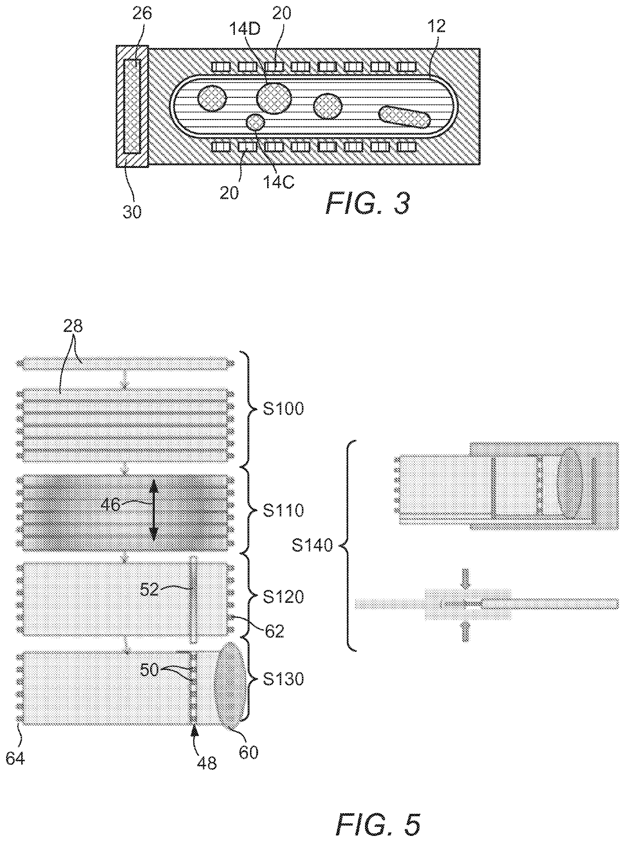
CROSS-REFERENCE TO RELATED APPLICATIONS[0001]This application is a continuation of U.S. patent application Ser. No. 13 / 529514, filed Jun. 21, 2012, which claims the benefit of U.S. Provisional Application No. 61 / 571,129, filed Jun. 21, 2011, each of which is incorporated in its entirety herein by reference.GOVERNMENT LICENSE RIGHTS[0002]This invention was made with government support under Grant No. 2R01-Ns 032845-10 awarded by the National Institute of Health. The government has certain rights in the invention.BACKGROUND OF THE INVENTION[0003]1. Field of the Invention[0004]This application relates generally to a method and apparatus for monitoring electrical signals conducted by a nerve and, more specifically, to an in-vivo nerve interface comprising an electrode array, a method of utilizing signals sensed by the electrode array to control a prosthetic device, and a method of fabricating the electrode array.[0005]2. Description of Related Art[0006]Despite great advances in many are...

Claims


Application Information

Patent Timeline
Patent Type & Authority Patents(United States)
IPC IPC(8): A61B5/00A61B5/0488A61N1/36A61N1/05A61F2/48
CPCA61N1/36135A61N1/36167A61N1/0556A61B5/00A61B5/4851A61B5/686A61B5/6877A61B5/0488A61N1/36125A61B2505/09A61B5/6887A61B2562/043A61F2002/482A61B5/4052A61B5/389A61F2/482A61B5/395
Inventor DURAND, DOMINIQUE M.WODLINGER, BRIAN
Owner CASE WESTERN RESERVE UNIV
Learn More