

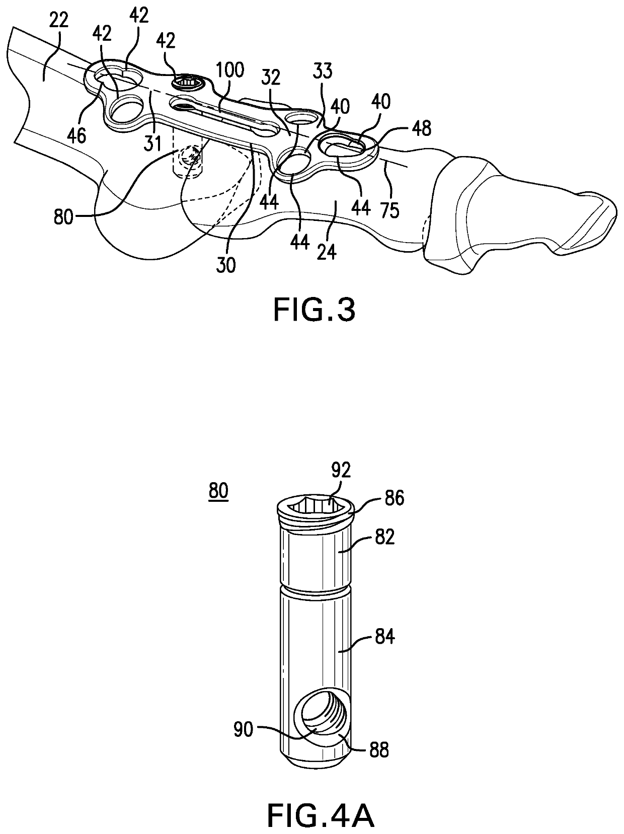
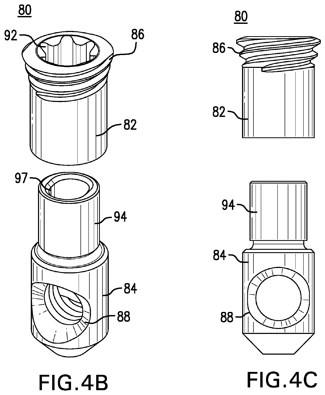
Orthopedic plate with modular peg and compression screw
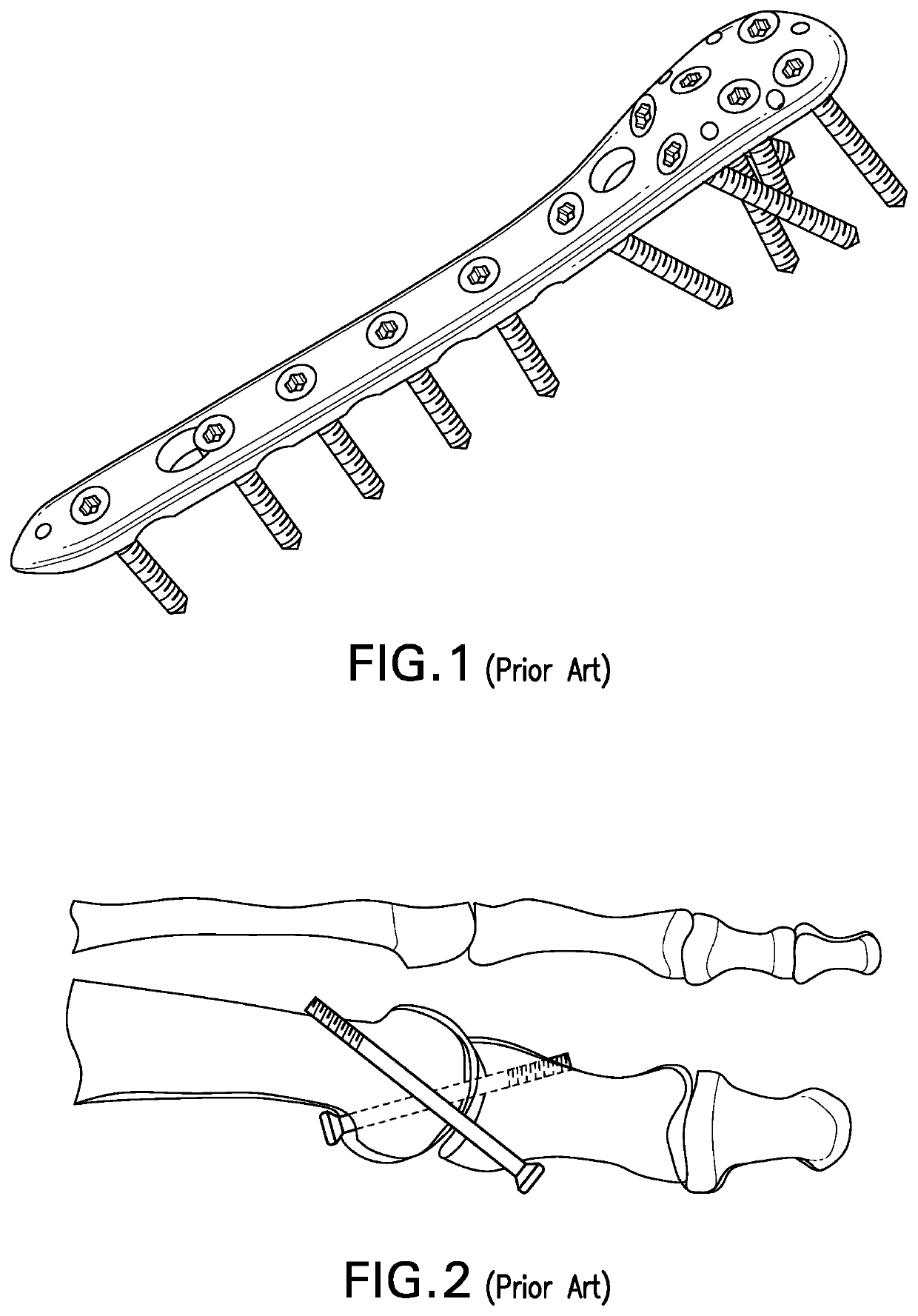
a technology of orthopedic plates and screws, applied in the field of bone fixation devices, can solve the problems of difficult to determine, reduce the exposed bone area, and limit the angle at which compression screws may be implanted
- Summary
- Abstract
- Description
- Claims
- Application Information
AI Technical Summary
Benefits of technology
Problems solved by technology
Method used
Image

Examples
Embodiment Construction
[0033]The invention may be understood more readily by reference to the following detailed descriptions of embodiments of the invention. However, techniques, systems, and operating structures in accordance with the invention may be embodied in a wide variety of forms and modes, some of which may be quite different from those in the disclosed embodiments. Also, the features and elements disclosed herein may be combined to form various combinations without exclusivity, unless expressly stated otherwise. Consequently, the specific structural and functional details disclosed herein are merely representative. Yet, in that regard, they are deemed to afford the best embodiment for purposes of disclosure and to provide a basis for the claims herein, which define the scope of the invention. It must be noted that, as used in the specification and the appended claims, the singular forms “a”, “an”, and “the” include plural referents unless the context clearly indicates otherwise.
[0034]As shown i...
PUM
 Abstract
Description
Claims
Application Information