Compact ultra-short pulsed laser eye surgery workstation

a workstation and ultra-short pulse technology, applied in the field of eye surgery, can solve the problems of large storage space and cumbersome maintenance, large storage space of conventional ultra-short pulsed laser systems, and large storage space of conventional ultra-short pulsed laser systems, and achieve the effect of reducing or eliminating mechanical vibration

Active Publication Date: 2020-09-22
AMO DEVMENT
View PDF27 Cites 8 Cited by
  • Summary
  • Abstract
  • Description
  • Claims
  • Application Information

AI Technical Summary

Benefits of technology

[0018]In some embodiments, the xy scan device may be a movable xy scanning stage having a final focusing objective mounted thereon. The movable xy-scanning stage may be a recoilless stage configured to reduce or eliminate mechanical vibration. The xy-scanning stage may be configured to move the pulsed laser beam in a lateral direction such that the laser beam covers the entire surgical field of the patient's eye.

Problems solved by technology

Conventional ultra-short pulsed laser systems are typically large, bulky, and complex, requiring significant storage space and cumbersome maintenance.
As would be expected, these systems require large room for storage.
Moreover, because these conventional laser machines are large and contain complex optics, they often require a mechanical arm such as an articulating arm or a gantry to support the optical head.
The complexity of the opto-mechanical design is further exacerbated due to safety and accuracy requirements for the mechanical arm configuration.
And, their large footprint and complexity in turn makes these conventional ultra-short pulsed laser systems costly to manufacture as well as to maintain.
Most of these laser systems are fixed systems, however, so moving them from room-to-room is not a feasible option.
Further, moving the system from room-to-room may not be preferred because the systems have complex and sensitive optical components.
Having the systems located in different rooms impacts workflow.

Method used


Image

  • Compact ultra-short pulsed laser eye surgery workstation
  • Compact ultra-short pulsed laser eye surgery workstation
  • Compact ultra-short pulsed laser eye surgery workstation

Examples


Embodiment Construction

[0048]Embodiments of this invention are generally directed to systems and methods for laser-assisted ophthalmic procedures.

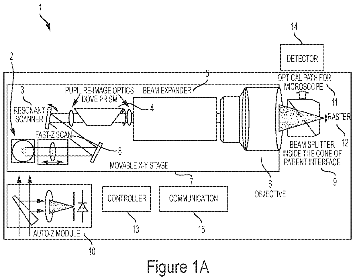
[0049]Referring to the drawings, FIG. 1A shows an ophthalmic surgical laser system 1 for making an incision in a target material such as a cornea of an eye. A laser 2 may comprise a femtosecond laser capable of providing pulsed laser beams, which may be used in optical procedures, such as localized photodisruption (e.g., laser induced optical breakdown). Localized photodisruptions can be placed at or below the surface of the material to produce high-precision material processing. The laser may be a micro-chip picosecond laser. For example, a laser beam delivery system may be used to scan the pulsed laser beam to produce an incision in the material, create a flap of material, create a pocket within the material, form removable structures of the material, and the like. The term “scan” or “scanning” refers to the movement of the focal point of the pulsed laser beam...


PUM


Abstract

A compact system for performing laser ophthalmic surgery is disclosed. An embodiment of the system includes a mode-locked fiber oscillator-based ultra-short pulsed laser capable of producing laser pulses in the range of 1 nJ to 5 μJ at a pulse repetition rate of between 5 MHz and 25 MHz, a resonant optical scanner oscillating at a frequency of 200 Hz and 21000 Hz, a scan-line rotator, a movable XY-scan device, a z-scan device, and a controller configured to coordinate with the other components of the system to produce one or more desired incision patterns. The system also includes compact visualization optics for in-process monitoring using a beam-splitter inside the cone of a patient interface used to fixate the patient's eye during surgery. The system can be configured such that eye surgery is performed while the patient is either sitting upright, or lying on his or her back.

Description

CROSS-REFERENCE TO RELATED APPLICATIONS[0001]This application is a non-provisional application and claims the benefit under 35 U.S.C. § 119(e) of U.S. Provisional Application Ser. No. 62 / 183,637, filed Jun. 23, 2015, which is incorporated herein in its entirety by reference.TECHNICAL FIELD[0002]Embodiments of this invention generally relate to the field of eye surgery, and more specifically to ophthalmic laser surgery using a mobile, compact surgical system having a mode-locked fiber oscillator-based ultra-short pulsed laser, a resonant optical scanner, a scan-line rotator, a movable XY-scanning stage, a z-scan mechanism, a controller, and compact visualization optics. The system can be configured such that eye surgery can be performed while the patient is in supine position. Alternatively, the system may be configured so that surgery is performed while the patient is sitting up in an upright position.BACKGROUND[0003]Vision impairments such as myopia (near sightedness), hyperopia (f...

Claims


Application Information

Patent Timeline
Patent Type & Authority Patents(United States)
IPC IPC(8): A61F9/008A61F9/009
CPCA61F9/0084A61F9/009A61F9/00814A61F2009/00872A61F2009/00897A61F2009/0087
Inventor FU, HONGMOORE, BRYANT M.VICE, CHARLES
Owner AMO DEVMENT
Why Eureka
Try Eureka