
Flexible printed circuit board and display module using the same

a printed circuit board and display module technology, applied in the direction of printed circuit non-printed electric components, coupling device connections, instruments, etc., can solve the problems of damage or torn flexible printed circuit boards

Active Publication Date: 2020-09-22
LG DISPLAY CO LTD
View PDF3 Cites 0 Cited by
  • Summary
  • Abstract
  • Description
  • Claims
  • Application Information

AI Technical Summary

Benefits of technology

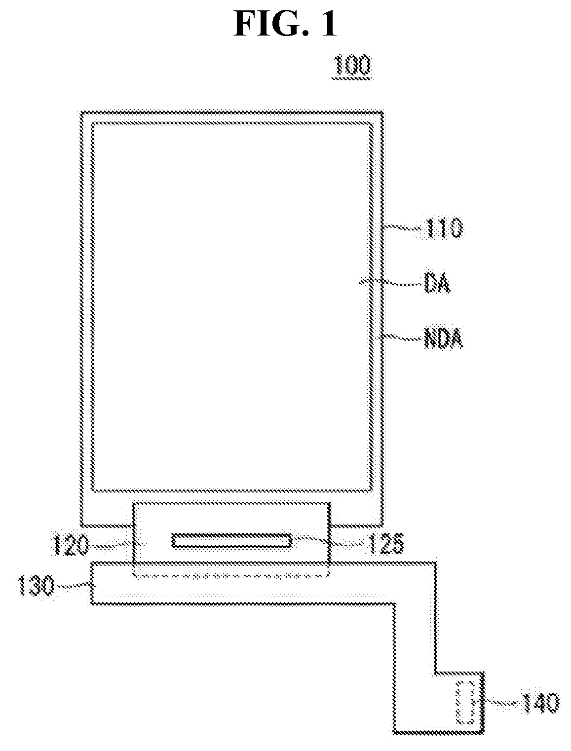
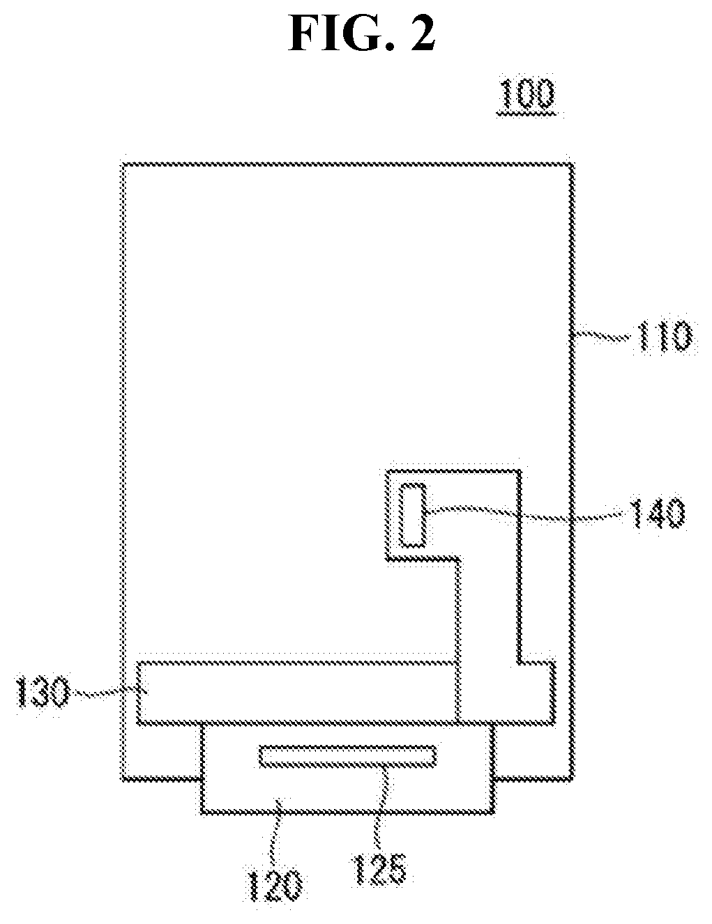
[0006]In order to solve such problems, inventors of the present disclosure contrive a flexible printed circuit board capable of increasing a fixing force between the flexible printed circuit board and the inspection jig so that the flexible printed circuit board may be stably seated on the inspection jig.
[0007]A problem to be solved according to an embodiment of the present disclosure, it is to provide a flexible printed circuit board and a display module having the same, capable of preventing the flexible printed circuit board from being detached or separated from an inspection jig in a fixing state of the flexible printed circuit board and the inspection jig as well as being torn upon attachment and detachment of the flexible printed circuit board, by forming holes or indents in locations where the flexible printed circuit board is capable of easily separated or detached from the inspection jig.

Problems solved by technology

And also the flexible printed circuit board is damaged or torn by the detachment and attachment of the flexible printed circuit board during the repeated inspection processes.

Method used


Image

  • Flexible printed circuit board and display module using the same
  • Flexible printed circuit board and display module using the same
  • Flexible printed circuit board and display module using the same

Examples


first embodiment

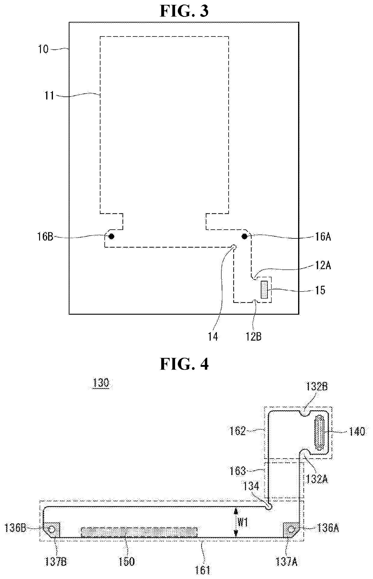
[0052]FIG. 4 is a plan view illustrating a flexible printed circuit board according to the disclosure.

[0053]The flexible printed circuit board 130 according to the first embodiment of the disclosure may include a first portion 161, a second portion 162 and a third portion 163. The first portion 161 is attached to the flexible film 120, the second portion 162 includes a connector 140 for receiving external signals, and the third portion 163 connects the first portion 161 to the second portion 162. Herein, the shape formed by the second portion 162 and the third portion 163 is ‘L-’ shape, but is not limited thereto.

[0054]The first portion 161 includes an attachment portion 150 to be attached to the flexible film 120. The attachment portion 150 is a region in which anisotropic conductive film is disposed to attach the flexible film 120 to the flexible printed circuit board 130. The attachment portion 150 may have a width which is at least 10% to less than 30% of the width W1 of the fle...

second embodiment

[0062]The flexible printed circuit board 230 according to the present disclosure may include a first portion 261, a second portion 262, and a third portion 263. The first portion 261 is attached to the flexible film 120, the second portion 262 includes a connector 240 for receiving external signals, and the third portion 263 connects the first portion 261 to the second portion 262. Herein, the shape formed by the second portion 262 and the third portion 263 is ‘’ shape, but is not limited thereto.

[0063]The first portion 261 of the flexible printed circuit board 230 includes an attachment portion 250 to be attached to the flexible film 120. The attachment portion 250 is a region in which anisotropic conductive film is disposed to attach the flexible film 120 to the flexible printed circuit board 230. The width W2 of the flexible printed circuit board 230 according to the second embodiment of the present disclosure is longer than the width W1 of the flexible printed circuit board 130 ...

third embodiment

[0070]The flexible printed circuit board 330 according to the present disclosure may include a first portion 361, a second portion 362, and a third portion 363. The first portion 361 is attached to the flexible film 120, the second portion 362 includes a connector 340 for receiving external signals, and the third portion 363 connects the first portion 361 to the second portion 362. Herein, the shape formed by the second portion 362 and the third portion 363 is ‘’, but is not limited thereto.

[0071]The first portion 361 of the flexible printed circuit board 330 includes an attachment portion 350 to be attached to the flexible film 120. The attachment portion 350 is a region in which anisotropic conductive film is disposed to attach the flexible film 120 to the flexible printed circuit board 330. The width W3 of the flexible printed circuit board 330 according to the third embodiment of the present disclosure is longer than the width W1 of the flexible printed circuit board 130 accordi...


PUM


Abstract

A flexible printed circuit board and a display module are capable of enhancing a fixing force of the flexible printed circuit board to a display panel or an inspection jig, and prevent the flexible printed circuit board from being separated or detached as well as being torn upon attachment and detachment. The flexible printed circuit board includes a display panel including a display area and a non-display area; a flexible film attached to the display area and to which a driving unit is mounted; and a flexible printed circuit board attached to the flexible film and having a connector for receiving external signals, wherein the flexible printed circuit board includes: at least one hole fixing the flexible printed circuit board to a rear surface of the display panel by bending the flexible film; and at least one indent fixed to an inspection jig.

Description

CROSS-REFERENCE TO RELATED APPLICATION[0001]This application claims the benefit of Republic of Korea Patent Application No. 10-2017-0182635 filed on Dec. 28, 2017, the entire contents of which is incorporated herein by reference in its entirety.BACKGROUNDTechnical Field[0002]The present disclosure relates to a flexible printed circuit board, in particular, to a flexible printed circuit board for enhancing a fixing force of the flexible printed circuit board to a display panel or a inspection jig, and prevent the flexible printed circuit board from being torn upon detachment and separation thereof, and a display module having the flexible printed circuit board.Discussion of the Related Art[0003]A flexible printed circuit board (FPCB) enables miniaturization of parts and light weight of products, thereby meeting the trend of light, thin, short and small requirements and a high density requirement of electronic industry. Also, the flexible printed circuit board is expected to be in hig...

Claims


Application Information

Patent Timeline
Patent Type & Authority Patents(United States)
IPC IPC(8): H05K1/00H05K1/18G06F1/16H05K1/02
CPCH05K1/028G06F1/1652G06F1/1637G06F1/1658H05K1/189H05K1/147H01R12/77H05K2201/10128
Inventor EUN, JUHEE
Owner LG DISPLAY CO LTD
Learn More