Electronic brake system

a technology of electronic brakes and brake components, applied in the direction of brake systems, vehicle sub-unit features, braking components, etc., can solve the problems of inability to achieve braking, fluid loss, safety accidents, etc., and achieve the effect of improving stability and reliability of braking

Active Publication Date: 2020-09-29
HYUNDAI MOTOR CO LTD +1
View PDF27 Cites 0 Cited by
  • Summary
  • Abstract
  • Description
  • Claims
  • Application Information

AI Technical Summary

Benefits of technology

[0008]Accordingly, the present disclosure has been made keeping in mind the above problems occurring in the related art. The present disclosure is intended to propose an electronic brake system that allows effective braking pressure to be formed in response to occurrence of a minute leak in a hydraulic circuit, thereby improving stability and reliability for braking.
[0020]The electronic brake system configured as described above allows the effective braking pressure to be formed in response to occurrence of a minute leak in a hydraulic circuit, whereby the stability and reliability for braking is improved.

Problems solved by technology

However, when the fluid is lost because of the occurrence of a minute leak, a situation where the braking cannot be accomplished may occur.
However, when torque tightening is not performed at the time the brake tube is fastened or a difference in pressure change is not detected for the occurrence of a minute leak induced by a fine foreign matter, the fluid may be lost until a situation where the braking cannot be accomplished occurs.
Thereby, a safety accident may occur.

Method used


Image

  • Electronic brake system
  • Electronic brake system
  • Electronic brake system

Examples


Embodiment Construction

[0028]Hereinbelow, an electronic brake system according to various embodiments of the present disclosure is described in detail with reference to the accompanying drawings. Throughout the drawings, the same reference numerals refer to the same or like parts.

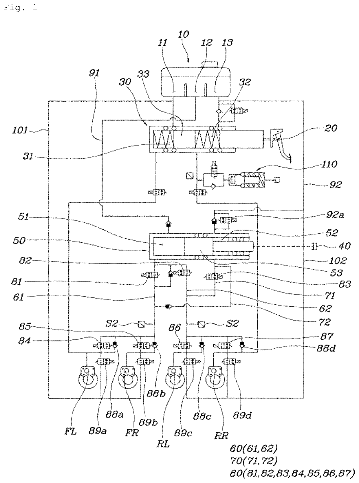
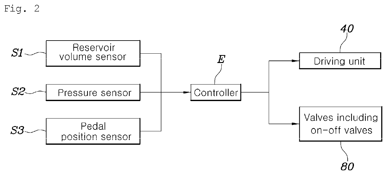
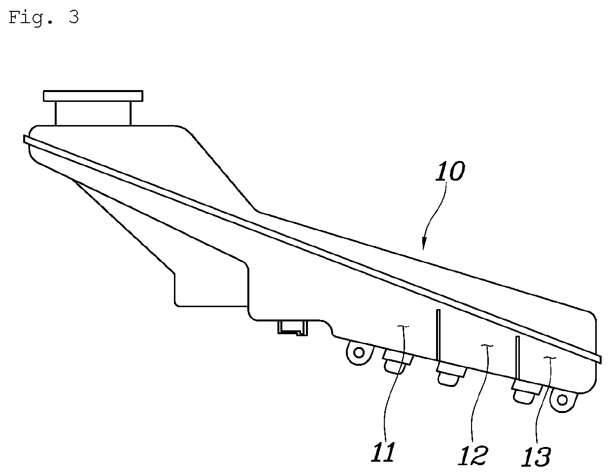
[0029]FIG. 1 is a hydraulic circuit diagram of an electronic brake system according to an embodiment of the present disclosure. FIG. 2 is a block diagram of the electronic brake system illustrated in FIG. 1. FIG. 3 is a view illustrating a reservoir of the present disclosure. FIG. 4 is a hydraulic circuit diagram illustrating the electronic brake system illustrated in FIG. 1. FIG. 5 is a graph illustrating driving of the hydraulic pressure supply cylinder of the present disclosure. FIG. 6 is a hydraulic circuit diagram illustrating the electronic brake system illustrated in FIG. 1.

[0030]As illustrated in FIGS. 1 and 2, the electronic brake system according to the present disclosure includes a reservoir 10 having a plurality of co...


PUM


Abstract

An electronic brake system allows the effective braking pressure to be formed in response to occurrence of a minute leak in a hydraulic circuit, whereby the stability and reliability for braking is improved.

Description

CROSS REFERENCE TO RELATED APPLICATION[0001]The present application claims priority to Korean Patent Application No. 10-2018-0159508, filed Dec. 11, 2018, the entire contents of which is incorporated herein for all purposes by this reference.BACKGROUNDField of the Disclosure[0002]The present disclosure relates to an electronic brake system, which allows effective braking pressure to be formed in response to occurrence of a minute leak in a hydraulic circuit.Description of the Related Art[0003]Generally, a brake system of an automobile using hydraulic pressure is a system for braking wheels by supplying hydraulic pressure generated in a master cylinder to a wheel brake installed on each wheel when a driver presses the brake pedal.[0004]Conventionally, a vacuum supplied from an engine has been used as a boosting pressure for increasing the braking pressure. However, electric vehicles and hybrid electric vehicles have been recently receiving increased attention of the market. As a resu...

Claims


Application Information

Patent Timeline
Patent Type & Authority Patents(United States)
IPC IPC(8): B60T13/68B60T17/06B60T8/17B60T13/14B60T17/22B60T13/58B60T8/171
CPCB60T17/221B60T8/171B60T8/17B60T13/58B60T13/145B60T13/686B60T17/06B60T2270/404B60T2270/402B60T2270/403B60T13/745B60T8/265B60Y2400/81
Inventor KIM, TAE HEON
Owner HYUNDAI MOTOR CO LTD
Why Eureka
Try Eureka