
Solenoid valve

Active Publication Date: 2021-09-16
HYUNDAI MOTOR CO LTD +1
View PDF0 Cites 0 Cited by
  • Summary
  • Abstract
  • Description
  • Claims
  • Application Information

AI Technical Summary

Benefits of technology

The present patent provides a solenoid valve that has improved stability and reliability, and also ensures leakproof sealability, improves accuracy of proportional control, and prevents abnormal operation of the valve member during an initial opening process due to rapid changes in pressure. Other technical effects include improved operational efficiency and reliability of the valve, as well as improved performance and accuracy of the control system.

Problems solved by technology

However, in the related art, during a process of initially opening the valve member (e.g., switching from a closed state of the valve member to an opened state of the valve member), the fluid, which presses a rear portion of the valve member to block the outlet flow path, rapidly flows into a front portion of the valve member, and thus the pressure changes (e.g., the pressure in the front portion of the valve member increases), which causes a difficulty to accurately control a movement stroke of the valve member and accuracy of proportional control for the valve member deteriorates.
Therefore, recently, various types of research is being conducted to ensure leakproof sealability of the solenoid valve and improve stability of proportional control, but the research result is still insufficient.
However, during a process of initially opening the valve member (e.g., switching from a closed state of the valve member to an opened state of the valve member), the fluid, which presses a rear portion of the valve member to block the outlet flow path, rapidly flows into a front portion of the valve member, and thus the pressure changes (e.g., the pressure in the front portion of the valve member increases), which causes difficulty in accurately controlling a movement stroke of the valve member and accuracy of proportional control for the valve member deteriorates.

Method used


Image

  • Solenoid valve
  • Solenoid valve
  • Solenoid valve

Examples


Embodiment Construction

[0035]It is understood that the term “vehicle” or “vehicular” or other similar term as used herein is inclusive of motor vehicles in general such as passenger automobiles including sports utility vehicles (SUV), buses, trucks, various commercial vehicles, watercraft including a variety of boats and ships, aircraft, and the like, and includes hybrid vehicles, electric vehicles, combustion, plug-in hybrid electric vehicles, hydrogen-powered vehicles and other alternative fuel vehicles (e.g. fuels derived from resources other than petroleum).

[0036]Although exemplary embodiment is described as using a plurality of units to perform the exemplary process, it is understood that the exemplary processes may also be performed by one or plurality of modules. Additionally, it is understood that the term controller / control unit refers to a hardware device that includes a memory and a processor and is specifically programmed to execute the processes described herein. The memory is configured to s...


PUM


Abstract

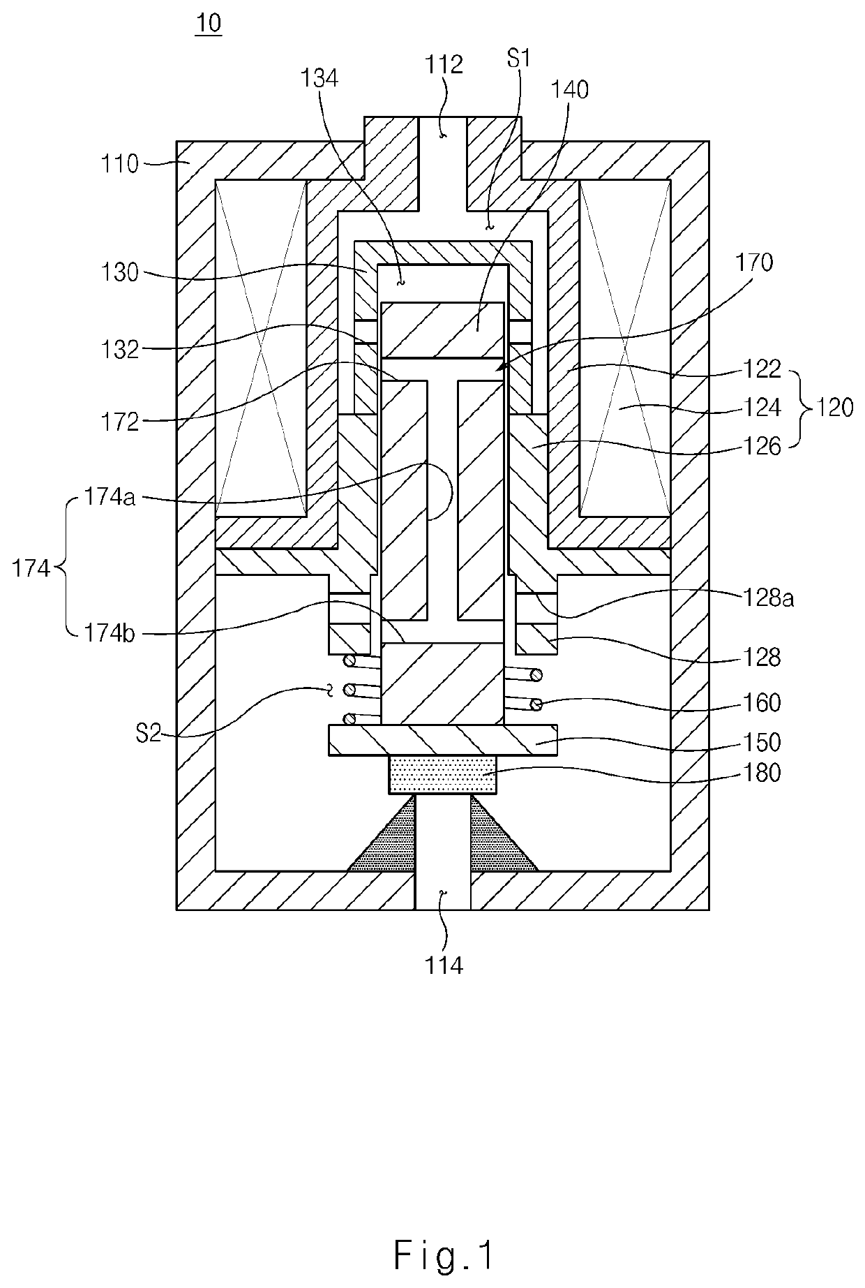
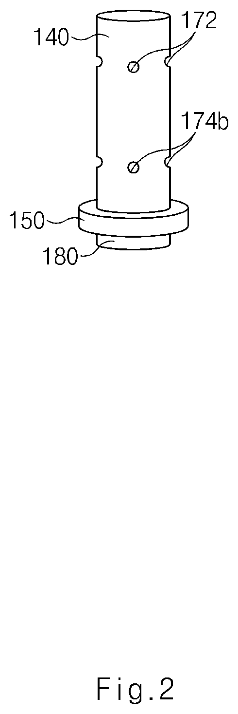
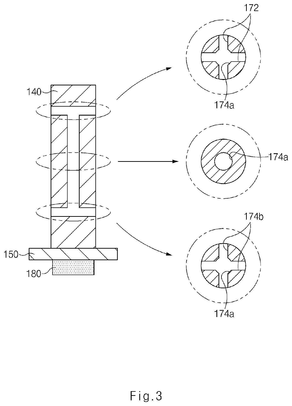
A solenoid valve includes a valve housing having a first space that communicates with an inlet flow path and a second space that communicates with an outlet flow path. A solenoid is provided in the valve housing to surround the first space. A flow path guide is provided in the first space and has an inflow path communicating with the first space. A plunger is rectilinearly moved in the flow path guide by the solenoid. A valve member is connected to the plunger and opens or closes the outlet flow path based on a plunger movement. A spring member provides elastic force allowing the valve member to move in a direction in which the valve member blocks the outlet flow path. A fluid guide part is formed in the plunger and guides a fluid, supplied into the inflow path via the first space, selectively to the second space.

Description

CROSS-REFERENCE TO RELATED APPLICATIONS[0001]This application claims priority to and the benefit of Korean Patent Application No. 10-2020-0032210 filed on Mar. 16, 2020, the entire contents of which are incorporated herein by reference.TECHNICAL FIELD[0002]The present disclosure relates to a solenoid valve, and more particularly, to a solenoid valve capable of improving stability and reliability.BACKGROUND ART[0003]A solenoid valve may be used to regulate a flow of a fluid or control a pressure. For example, a solenoid valve may be installed in a power train including an engine of a vehicle and serve to regulate a flow of a fluid such as fuel or oil or control a pressure. More specifically, a solenoid valve mounted in a fuel system may control an operation of supplying and injecting fuel, a solenoid valve mounted in a cooling system may control circulation for lubrication and cooling, and a solenoid valve mounted in a power transmission system may adjust a pressure.[0004]In general,...

Claims


Application Information

Patent Timeline
IPC IPC(8): F16K31/06F16K1/36
CPCF16K31/0658F16K31/0651F16K1/36F16K31/0675F16K31/0655F16K27/029F16K31/0693F01P7/14F16K2200/50F01P2007/146F01P7/16F02M63/0017F02M63/0078F16K17/04F16K27/02
Inventor PARK, IN TAEBAN, HYEON SEOKSHIM, HYO SUB
Owner HYUNDAI MOTOR CO LTD
Learn More