
Composite electro/optical microcable

a micro-cable and optical technology, applied in the field of optical micro-cables, can solve the problems of greatly limited data exchange rate among electronic components, and achieve the effects of improving data exchange rate and amount, simple structure, and small siz

Active Publication Date: 2016-11-01
EVERPRO TECH COMPANY
View PDF20 Cites 0 Cited by
  • Summary
  • Abstract
  • Description
  • Claims
  • Application Information

AI Technical Summary

Benefits of technology

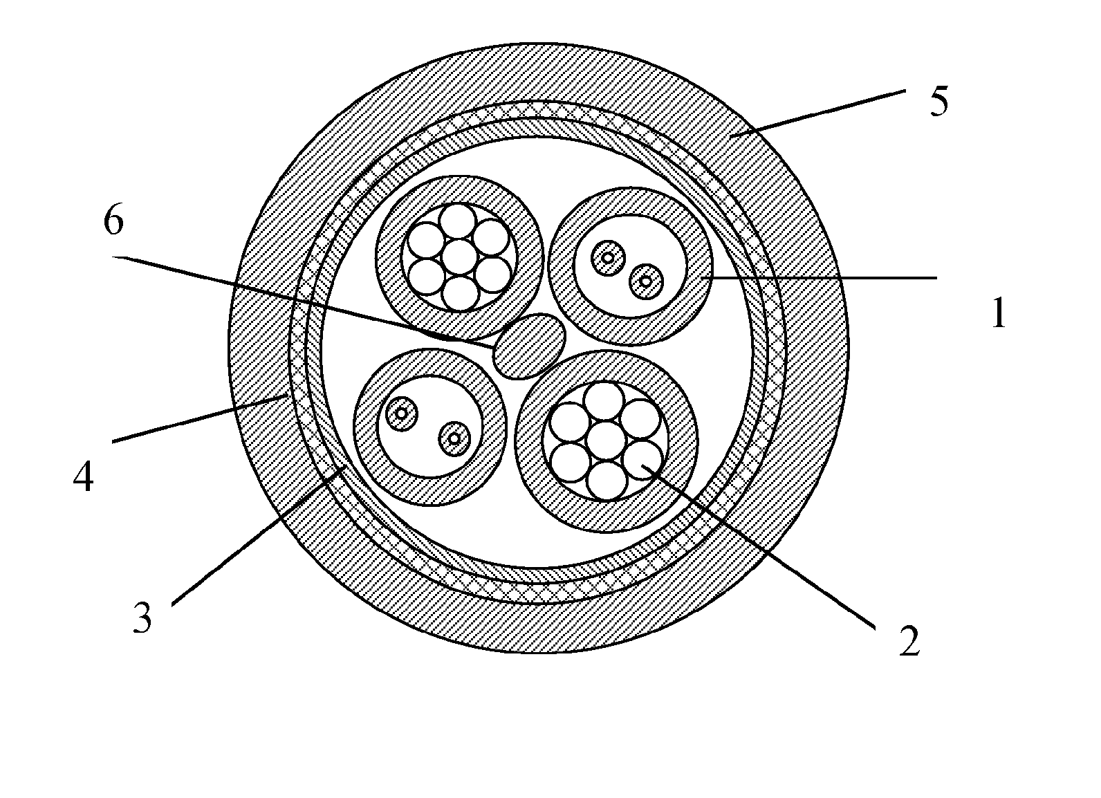
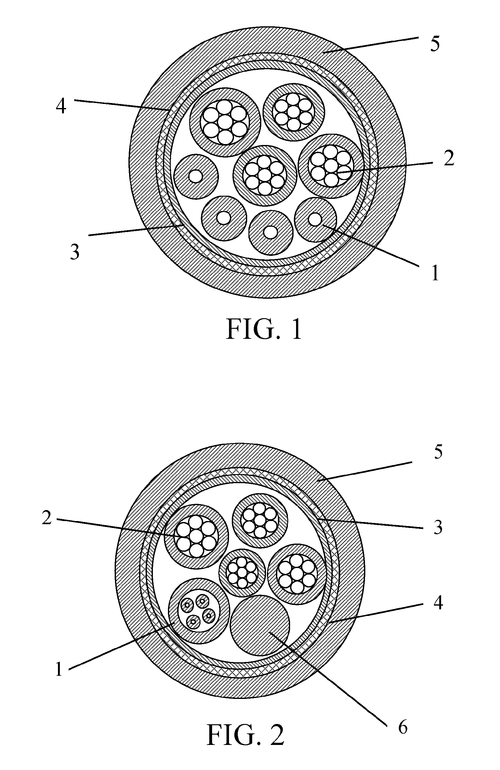
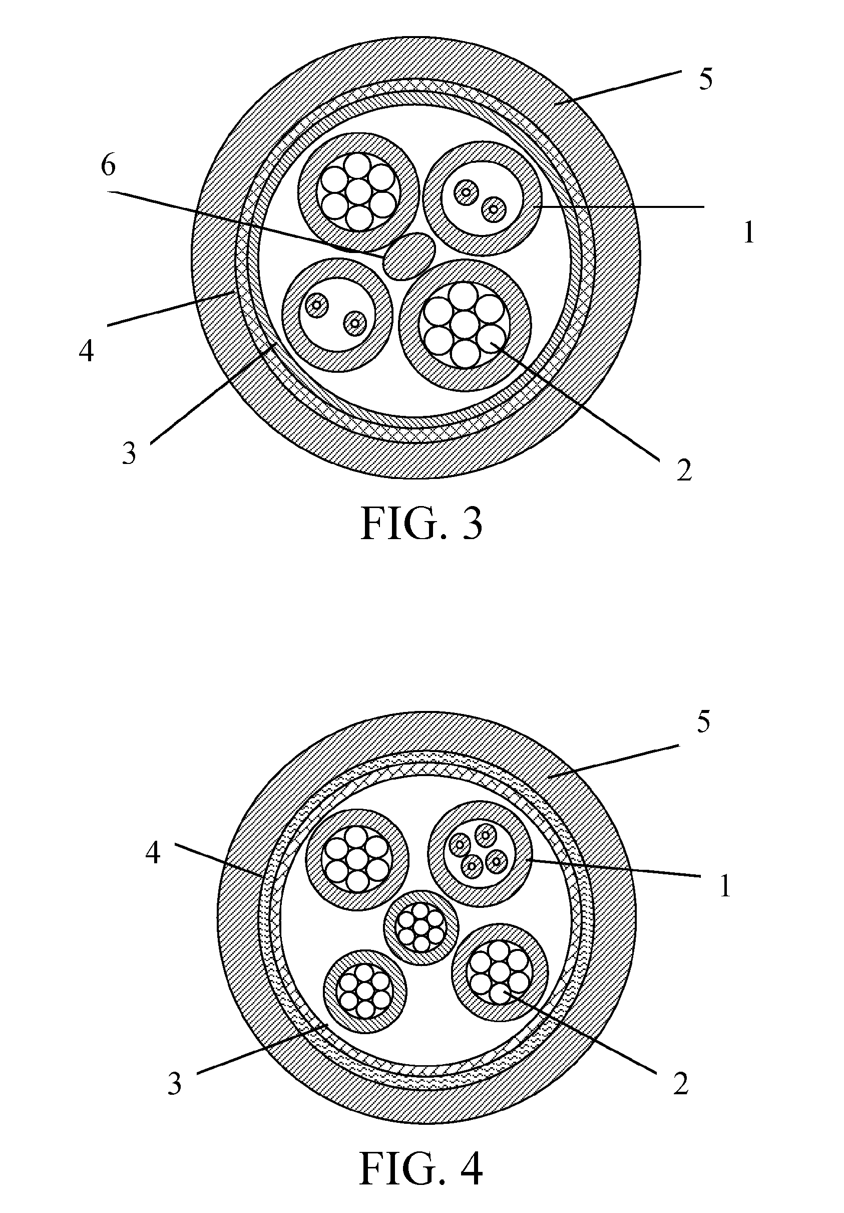
[0016]The present invention has, among other things, the following advantages. (1) Conductive metal wires, as elements for connection among electronic components in a transmission chain, are used for electric transmission among the electronic components, and an optical fiber is used for data transmission, which greatly improves a data exchange rate and amount among the electronic components, thereby meeting the requirement of transmitting high-definition video and audio signals at a data transmission rate exceeding 5 Gbps within about 200 meters. (2) The composite electro / optical microcable according to the present invention is simple in structure, small in size, light in weight, and superior in mechanical and bending properties. The composite electro / optical microcable is applicable to connection and conduction among the electronic components and products, and suitable for being used in narrow spaces in computer hardware and components, and convenient to use, which makes the electro / optical communications and the consumer electronic products in future operate more rapidly in an electro / optical interface. (3) By utilizing a wrapping layer and a braided layer, mutual interference between electric signals is effectively avoided, thereby greatly improving stability and reliability of the signal transmission. (4) not only has the optical communication unit a desirable branch connection property, but other communication units have a desirable soldering property, thereby greatly facilitating fabrication of joints and connectors for the composite electro / optical cable.

Problems solved by technology

Due to limited amount and rate of the data transmission of the metal conductors, the data exchange rate among the electronic components is greatly limited.

Method used


Image

  • Composite electro/optical microcable
  • Composite electro/optical microcable
  • Composite electro/optical microcable

Examples


Embodiment Construction

[0023]The invention will now be described more fully hereinafter with reference to the accompanying drawings, in which exemplary embodiments of the invention are shown. This invention may, however, be embodied in many different forms and should not be construed as limited to the embodiments set forth herein. Rather, these embodiments are provided so that this disclosure will be thorough and complete, and will fully convey the scope of the invention to those skilled in the art. Like reference numerals refer to like elements throughout.

[0024]The terms used in this specification generally have their ordinary meanings in the art, within the context of the invention, and in the specific context where each term is used. Certain terms that are configured to describe the invention are discussed below, or elsewhere in the specification, to provide additional guidance to the practitioner regarding the description of the invention. For convenience, certain terms may be highlighted, for example...


PUM


Abstract

In one aspect of the invention, the composite electro / optical microcable includes an outer sheath, and a composite electro / optical core covered by the outer sheath. The composite electro / optical core includes a strand of an insulated conductive wire set and an optical fiber unit, and a wrapping layer wrapping the strand of the insulated conductive wire set and the optical fiber unit. The insulated conductive wire set comprises one or more insulated conductive wires, each insulated conductive wire comprising one or more metal wires and an insulating layer covering the one or more metal wires. The optical fiber unit includes one or more optical fibers, one or more tight-buffered optical fiber cables, or one or more optical fiber ribbons.

Description

CROSS-REFERENCE TO RELATED APPLICATIONS[0001]This application is a continuation application of International Patent Application No. PCT / CN2013 / 085391, filed Oct. 17, 2013, which itself claims the priority to Chinese Patent Application No. 201220541032.9, filed Oct. 22, 2012 in the State Intellectual Property Office of P.R. China, which are hereby incorporated herein in their entireties by reference.FIELD OF THE INVENTION[0002]The present invention relates generally to a composite electro / optical microcable for connection and conduction among electronic components, which makes data signal transmission among the electronic components enter an optical communication phase.BACKGROUND OF THE INVENTION[0003]The background description provided herein is for the purpose of generally presenting the context of the present invention. The subject matter discussed in the background of the invention section should not be assumed to be prior art merely as a result of its mention in the background o...

Claims


Application Information

Patent Timeline
Patent Type & Authority Patents(United States)
IPC IPC(8): G02B6/44
CPCG02B6/4416G02B6/4436G02B6/449G02B6/4413
Inventor RUAN, YUNFANGLI, MINGANGSU, XIAOFANCHEN, FENGXIONG, ZHUANG
Owner EVERPRO TECH COMPANY
Learn More