Method for producing a flash coving profile and method for arranging the obtained flash coving profile in the corner between a floor and a wall

a coving profile and coving technology, applied in the direction of adhesives, flooring, construction, etc., can solve the problems of requiring special installation skills, affecting the appearance of the coving profile, so as to facilitate the creation of the abutting

Active Publication Date: 2020-09-29
FORBO FLOORING BV
View PDF12 Cites 5 Cited by
  • Summary
  • Abstract
  • Description
  • Claims
  • Application Information

AI Technical Summary

Benefits of technology

[0012]In the invention, the fillet-shaped cove former (made of a metal sheet) is provided with a layer of flexible and preferably resilient flooring to a first face of the metal sheet after which this combination is bent into a cove before adhering the flash coving profile to the wall. This increases the ease of production of the flash coving profile, which is substantially L-shaped and has a first section or leg to be adhered to a wall and a second section or leg to be adhered to a subfloor. The cove is preferably bent into the metal sheet by roller forming.
[0032]In this method, it is preferred to first arrange and fix the flash coving profile according to the invention in the corner between a wall and a floor before the provision of the further flooring. This increases the ease of creation of an abutting connection between the flooring adhered of the coving profile and the further flooring.

Problems solved by technology

Both procedures have the disadvantage of being complex, requiring specialized installation skills.
Furthermore, the cove former strip or the flooring may be damaged by pressing the flooring to hard against the cove former strip in the corner.
However, in such cases, the fixed position of the pre-installed cove cap limits the flexibility in fitting the cove former strip and furthermore increases the risk of misalignment of the cove former strip between the pre-installed cove cap and the pre-installed main flooring.
The production of this flash coving profile is relatively costly due to the complex shape of the profile.

Method used


Image

  • Method for producing a flash coving profile and method for arranging the obtained flash coving profile in the corner between a floor and a wall
  • Method for producing a flash coving profile and method for arranging the obtained flash coving profile in the corner between a floor and a wall

Examples


Embodiment Construction

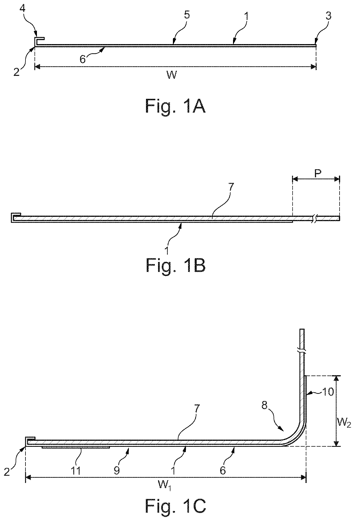
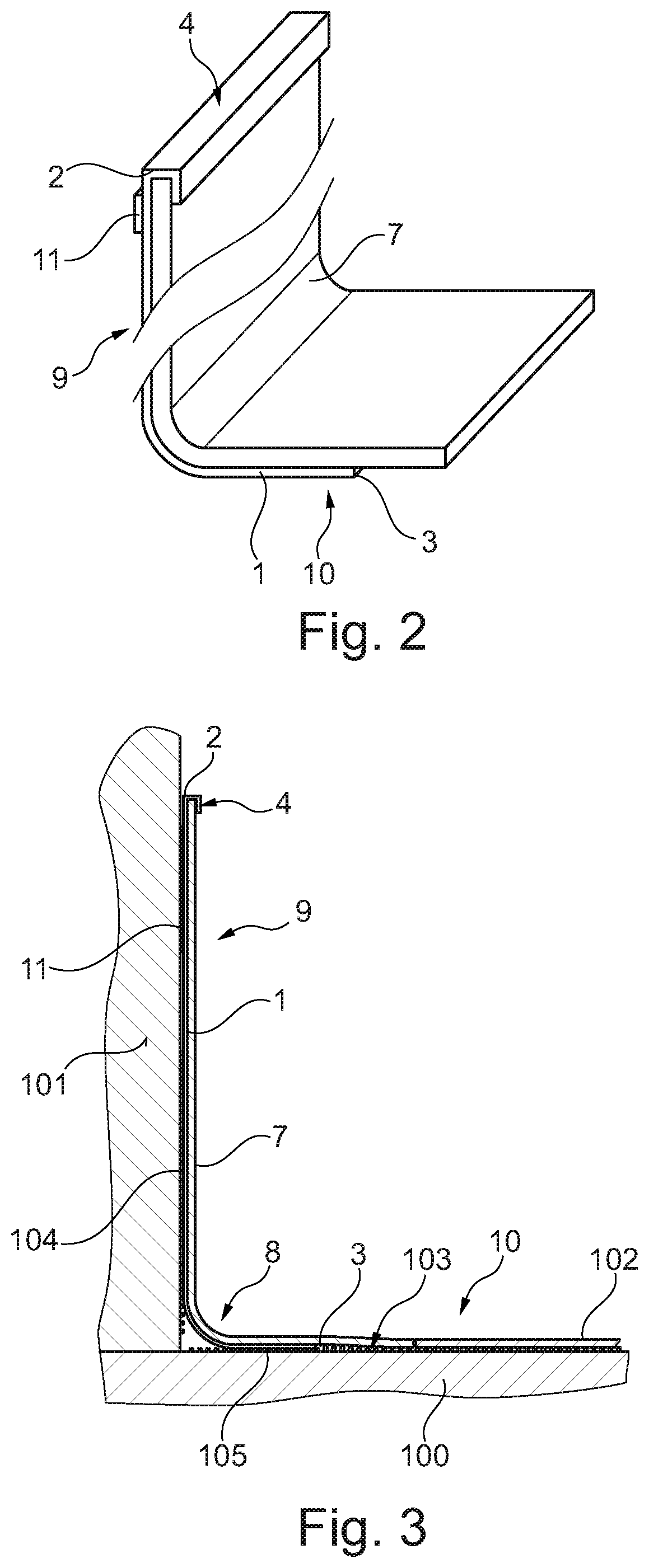
[0039]The method for forming a flash coving profile according to the invention is disclosed in FIG. 1. The method starts, as shown in FIG. 1A, with a metal sheet 1 with a first edge 2 and a second edge 3, with a width W of approximately 200 millimeters. The length of the sheet 1, which runs perpendicular to the plane of the drawing, is typically between 2.4 and 3.7 meters. A zone adjacent to the first edge 2 is folded into a U-shaped cove cap 4. The metal sheet has a first face 5 and an opposing second face 6. Then, a layer of flooring 7 is adhered to the first face 5 of the metal sheet 1, protruding from the second edge 3 to a width P of between 50 and 150 millimeters. After that, a cove 8 with a radius of 12 to 26 millimeter is bent into the metal sheet along a bend line parallel to the first edge 2 and second edge 3, to obtain an L-shaped coving profile which has a first section 9 extending from the first edge to the cove 8, to be adhered to a wall, and a second section 10 extend...


PUM


Abstract

The invention relates to a method for producing a flash coving profile, including the steps of: providing an elongate metal sheet with a first longitudinal edge and a second edge opposing, and preferably parallel to, the first edge; adhering a flexible and preferably resilient flooring to a first face of the metal sheet, the flooring extending from the first edge to at least the second edge; and bending a cove into the metal sheet with the flooring adhered to it along a bend line which is parallel to and spaced apart from the first edge and on the side to which the flooring is adhered. The invention further relates to a method for arranging a flash coving profile obtained by the method according to the invention in the corner between a floor and a wall.

Description

CROSS-REFERENCE TO RELATED APPLICATION[0001]This application claims priority to The Netherlands Patent Application No. 2021953 filed Nov. 7, 2018, the disclosure of which is hereby incorporated by reference in its entirety.BACKGROUND OF THE INVENTIONField of the Invention[0002]The invention relates to a method for producing a flash coving profile.Description of Related Art[0003]For different applications, it is common to apply a flexible flooring such as resilient flooring to a subfloor. Typically, it is not desirable to use the same flooring to cover the entire adjacent wall, but still it is beneficial to create a smooth transition between the subfloor and the wall which is less likely to collect dust. To this purpose, it is known to flash cove the flooring up to the wall.[0004]Traditionally, when flash coving, an upside-down U-shaped cove cap is fixed to the wall (e.g. with adhesive tape or contact cement) and a flexible vinyl or metal fillet-shaped cove former strip is arranged b...

Claims


Application Information

Patent Timeline
Patent Type & Authority Patents(United States)
IPC IPC(8): E04F19/04E04F19/06
CPCE04F19/04E04F19/061E04F2019/0413E04F15/02155E04F15/06E04F15/16E04F19/045E04F19/0477E04F2019/0422E04F2019/0431
Inventor LAVALLIE, DANNY DENNISKONTOSIC, JOHNNY
Owner FORBO FLOORING BV
Why Eureka
Try Eureka