
Hot runner injection nozzle and drive train

a technology of injection nozzle and drive train, which is applied in the field of hot runner injection nozzle, can solve the problems of not being able to ensure that the required specifications are met, and achieve the effects of avoiding unwanted tilting, good results, and good results

Active Publication Date: 2020-10-13
OTTO MANNER
View PDF6 Cites 0 Cited by
  • Summary
  • Abstract
  • Description
  • Claims
  • Application Information

AI Technical Summary

Benefits of technology

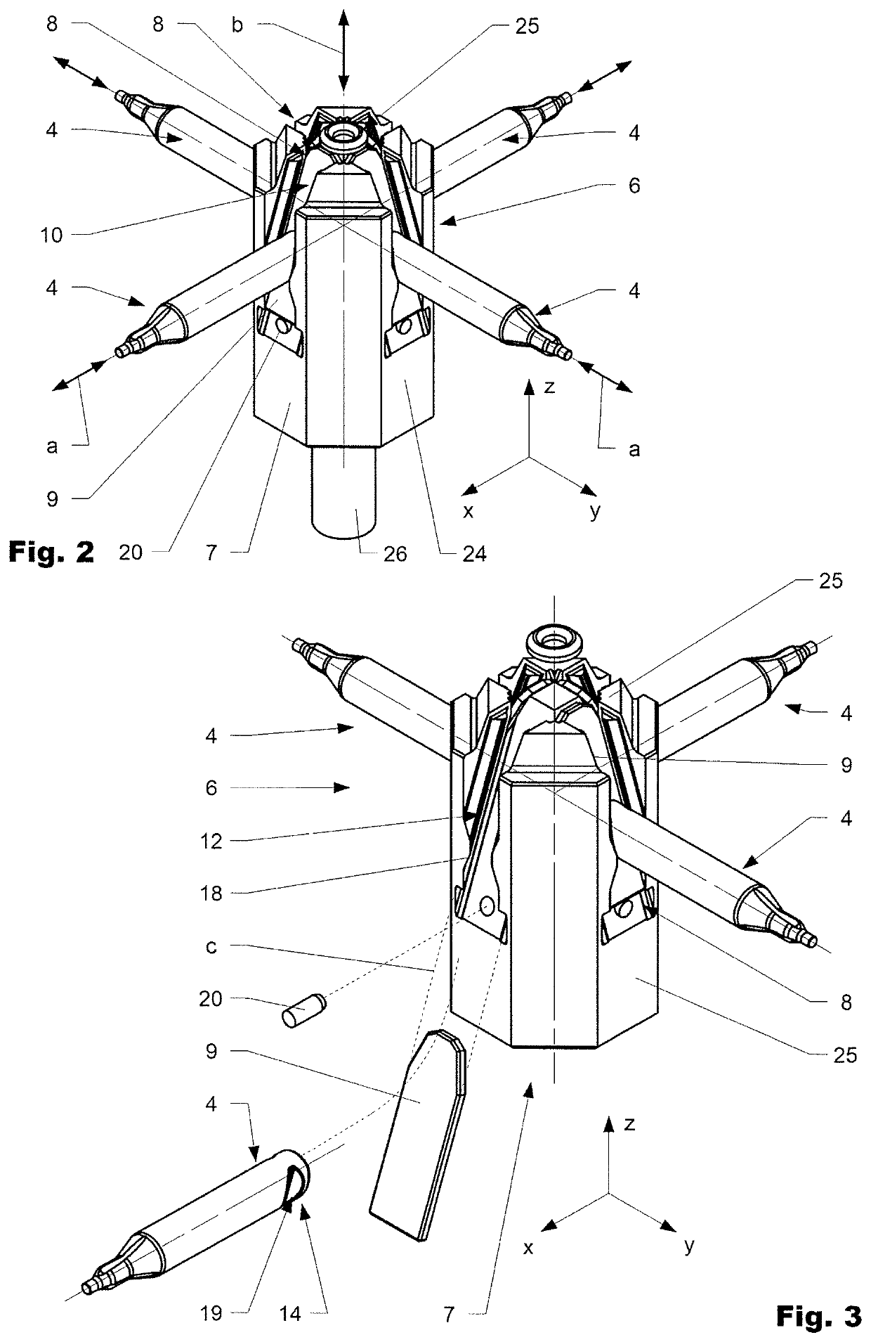
[0008]An injection nozzle according to the invention normally comprises an actuator inter-connected via a drive train to at least one closure element arranged movable in a nozzle head in a first direction. The drive train comprises a cam mechanism with a cam head with a cam head block. The cam head block normally comprises per closure element a bracket which is foreseen to receive at least one inlay. The inlay is primarily foreseen to improve the wear behavior of the injection nozzle especially under harsh conditions as it protects the cam head block from direct contact at least in one direction of movement. The at least one inlay is preferably made from at least one material out of the following group of materials or a combination thereof: tungsten carbide or ceramic.
[0014]The inlay preferably is a pad, preferably having a rectangular pad shape. Good results can be achieved when it is arranged in the area of the bottom of the recess. Depending on the particular design it can be inserted into the related bracket in depth direction of the recess. In a preferred variation the inlay is inserted in longitudinal direction of the recess. To securely hold the inlay in the recess, the side surfaces of the recess may have protrusions forming undercuts in vertical direction behind which the inlay can be inserted in longitudinal direction. Behind, the pad shaped inlay in depth direction of the recess can be directly supported by the bottom surface of the recess. The inlay can be locked in longitudinal direction of the recess e.g. by a bolt or a welding spot or another appropriate means which avoids movement of the inlay in longitudinal direction. Alternatively or in addition the inlay can be clamped.
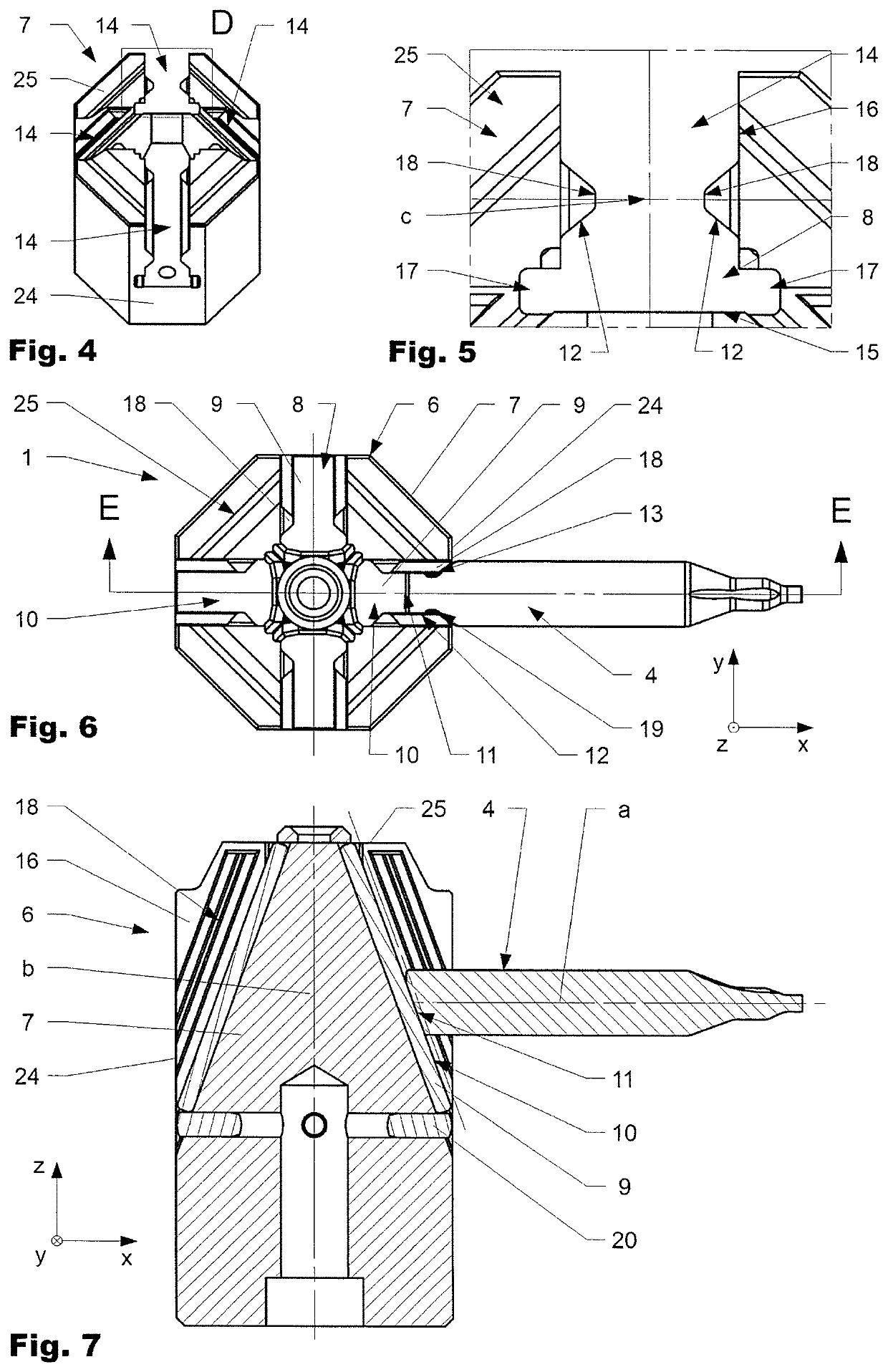
[0015]The first drive surface of the inlay and the corresponding third drive surface of the cam head block are normally arranged at an angle with respect to the second direction as mentioned above. Good results can be achieved when the angle is in the range of 10° to 30°. Depending on the field of application, other values are possible. Good results are achieved when the third drive surface are arranged at a protrusion of the at least one side surface of the recess, extending parallel to and spaced a distance apart from the first drive surface provided by the inlay. The fourth drive surface can be arranged at a shoulder or in a notch arranged at the closure element. The area of the second drive surface preferably is larger than the sum of the areas of the at least one fourth drive surface. The cam head block and the at least one inlay are interconnected to each other by at least one bolt which is arranged in an opening. The cam head can comprise at least one bearing surface to support the cam head during operation with respect to the closure element housing to avoid unwanted tilting and distortion of the cam head with respect to the housing.
[0017]The thereto corresponding fourth drive surface is preferably arranged in a notch or at a shoulder arranged at the closure element. The protrusion and the thereto corresponding notch can have a V-shaped cross section resulting in a robust but yet precise interaction. In addition, it can have the positive effect of self-centering when arranged symmetric.

Problems solved by technology

Otherwise it cannot be guaranteed that the required specifications are met.

Method used


Image

  • Hot runner injection nozzle and drive train
  • Hot runner injection nozzle and drive train
  • Hot runner injection nozzle and drive train

Examples


Embodiment Construction

[0028]Reference will now be made in detail to certain embodiments, examples of which are illustrated in the accompanying drawings, in which some, but not all features are shown. Indeed, embodiments disclosed herein may be embodied in many different forms and should not be construed as limited to the embodiments set forth herein; rather, these embodiments are provided so that this disclosure will satisfy applicable legal requirements. Whenever possible, like reference numbers will be used to refer to like components or parts.

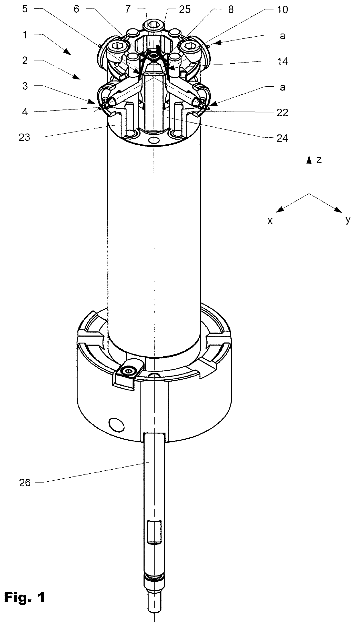
[0029]FIG. 1 shows an injection nozzle 1 in a perspective view in a partially cut manner. FIG. 2 shows a cam mechanism 5 in a perspective view. FIG. 3 shows the cam mechanism 5 in an exploded manner. FIG. 4 shows a cam head 6 in a perspective view. FIG. 5 is showing detail D according to FIG. 4. FIG. 6 is showing the cam head 6 in a top view and FIG. 7 is showing the cam head 6 in a section view according to section line E-E of FIG. 6.

[0030]An injection nozzle 1 ...


PUM

PropertyMeasurementUnit
angleaaaaaaaaaa
angleaaaaaaaaaa
angleaaaaaaaaaa

Abstract

An injection nozzle for an injection molding device comprising a nozzle head, an actuator, a drive train connected to the actuator, and at least one closure element. The drive train configured for moving the at least one closure element arranged in the nozzle head in a first direction. The drive train comprising a cam mechanism that comprises a cam head. The cam head comprising a cam head block. Per closure element, the cam head block comprising a bracket. The bracket comprising at least one inlay. Per closure element, the at least one inlay comprising a first drive surface configured for engaging and driving a second drive surface arranged at the closure element at least during closing of the closure element. Per closure element, the cam head block comprising a third drive surface configured f engaging and driving a fourth drive surface arranged at the closure element at least during opening of the closure element.

Description

BACKGROUND OF THE INVENTIONField of the Invention[0001]The present invention relates to a hot runner injection nozzle comprising a drive train to actuate a closure element by an actuator.Discussion of Related Art[0002]Hot runner nozzles comprising drive trains to actuate closure elements (valve pins) are known from the prior art. Several thereto related publications are briefly cited hereinafter.[0003]WO15150501A1 was first published in October 2015 in the name of the same applicant as the herein disclosed invention. It is directed to a hot runner nozzle for side gating in a hot runner injection molding apparatus. A nozzle that is connectable to a melt outlet opening of a hot runner manifold. It comprises a nozzle flange portion, a nozzle body portion and a nozzle bridge portion. The nozzle bridge portion has at least two adjacently arranged nozzle tip sections. At least two valve pins are coupled to a valve pin actuating device which is moveable back and forth along a first axis. T...

Claims


Application Information

Patent Timeline
Patent Type & Authority Patents(United States)
IPC IPC(8): B29C45/28B29C45/27
CPCB29C45/2735B29C45/281B29C2045/2858B29C2045/2831B29C45/2806B29C2045/2813B29C45/27B29C45/28
Inventor SPULLER, SWENBÄR, MARIUS
Owner OTTO MANNER
Learn More