
Short-range wireless communication system and short-range wireless communication device

a wireless communication system and wireless communication technology, applied in the field of short-range wireless communication system and short-range wireless communication device, can solve the problem of wasteful power consumption of unnecessary communication device, and achieve the effect of suppressing unnecessary power consumption

Active Publication Date: 2020-10-13
DENSO CORP
View PDF9 Cites 0 Cited by
  • Summary
  • Abstract
  • Description
  • Claims
  • Application Information

AI Technical Summary

Benefits of technology

The problem addressed by this patent is the unnecessary power consumption of multiple short-range wireless communication devices mounted on a vehicle. The patent proposes a system where only the devices located within the communication range of the main device, the mobile terminal, are activated, reducing unnecessary power consumption. This results in a more efficient use of power, particularly in a vehicle-mounted wireless communication system.

Problems solved by technology

However, in the configuration where the multiple short-range wireless communication devices are mounted on the vehicle, if all of the short-range wireless communication devices are kept activated although some communication devices are not necessary, power is wastefully consumed by the unnecessary communication devices.

Method used


Image

  • Short-range wireless communication system and short-range wireless communication device
  • Short-range wireless communication system and short-range wireless communication device
  • Short-range wireless communication system and short-range wireless communication device

Examples


first embodiment

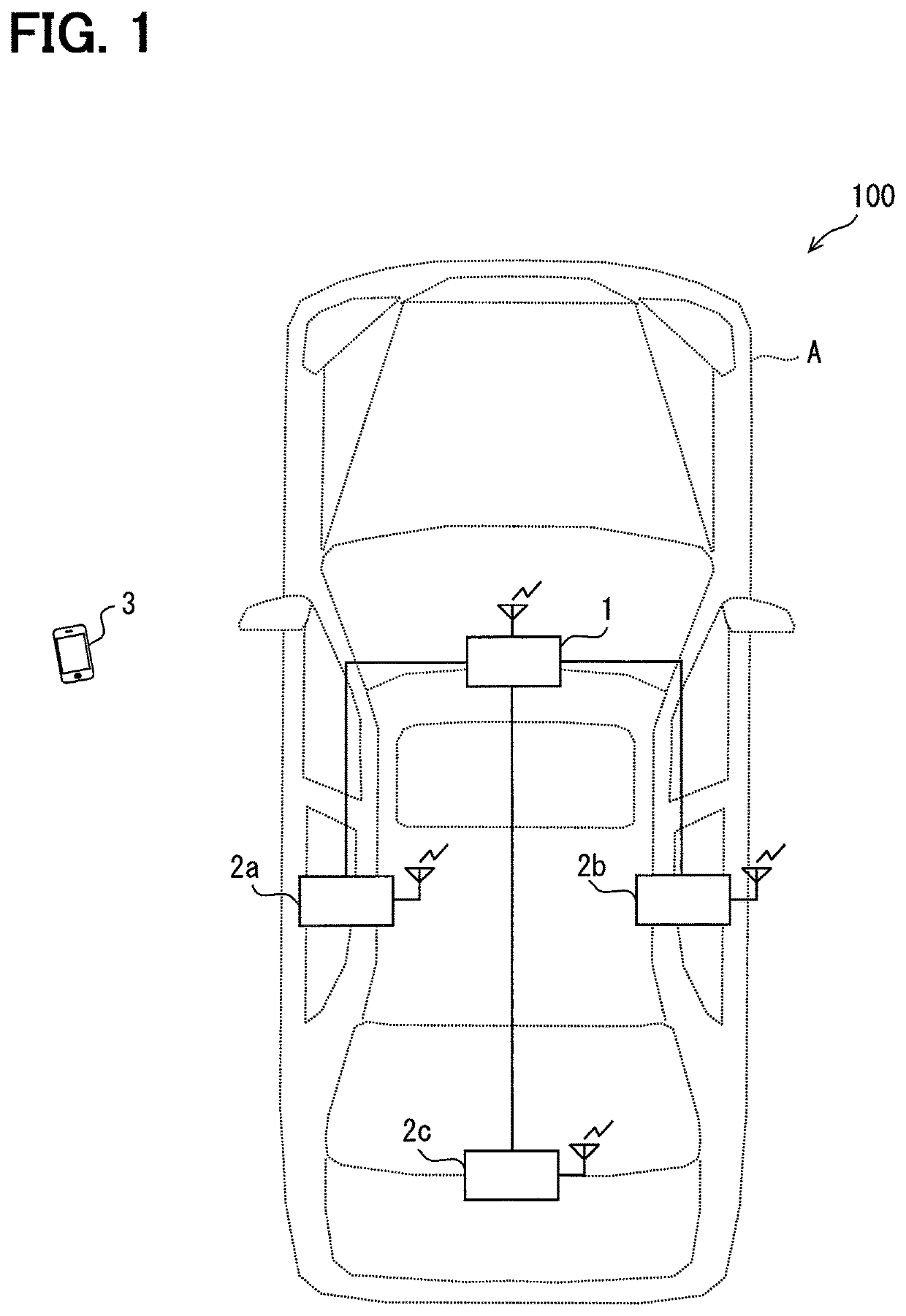
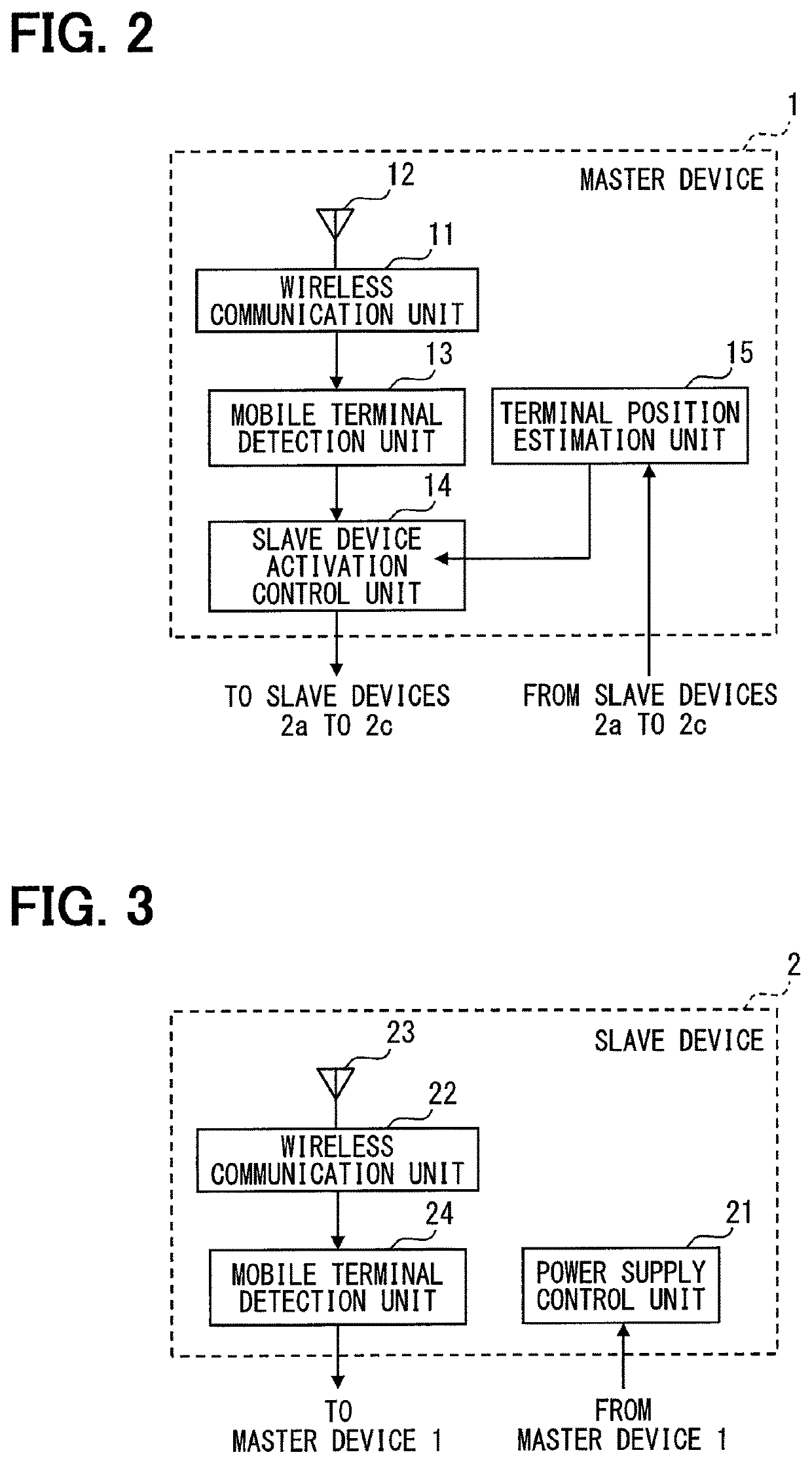
[0020]Hereinafter, embodiments of the present disclosure will be described with reference to the accompanying drawings. FIG. 1 is a diagram illustrating an example of a schematic configuration of a short-range wireless communication system 100 according to the present disclosure. As illustrated in FIG. 1, the short-range wireless communication system 100 includes a short-range wireless communication device (hereinafter referred to as “master device 1”) as a master device mounted on a vehicle A, multiple short-range wireless communication devices (hereinafter referred to as “slave devices 2a to 2c”) as slave devices mounted on the vehicle A, and a mobile terminal 3. The master device 1 is connected to the slave devices 2a to 2c through, for example, a vehicle LAN or the like. The master device and the slave devices 2a to 2c configure a short-range wireless communication system.

[0021]The mobile terminal 3 may be provided by, for example, a multifunctional cellular phone that can be ca...

first modification

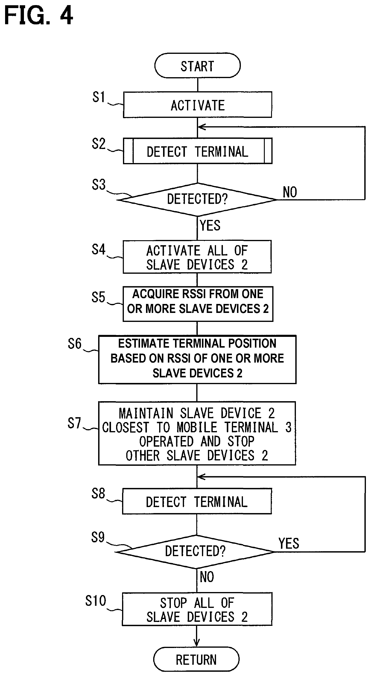
[0053]In the first embodiment, when the mobile terminal 3 is detected by the terminal detection of the mobile terminal detection unit 13, the slave device activation control unit 14 activates all of the slave devices 2 at the same time. However, the present disclosure is not limited to the above configuration. For example, a configuration (hereinafter referred to as first modification) in which the slave devices 2 are activated in order one by one may be used. For convenience of description, in the description subsequent to the first modification, members having the same functions as those of the members illustrated in the drawings used hereinbefore are denoted by identical symbols, and their description will be omitted.

[0054]For example, in first modification, when the mobile terminal 3 is detected by the terminal detection of the mobile terminal detection unit 13, the slave device activation control unit 14 may actuate the slave devices 2a to 2c sequentially at regular time interv...

second modification

[0059]The terminal detection executed by the mobile terminal detection unit 13 of the master device 1 may be configured to satisfy no condition, such as whether the RSSI of the radio waves received from the registered mobile terminal 3 is equal to or more than the threshold or not. In that case, in the flowchart of FIG. 5, the processing of S22 and S23 may be omitted, and if the determination in S21 is negative, the process may proceed to S25.


PUM


Abstract

A short-range wireless communication system mounted on a vehicle includes a master device and slave devices. Each of the master device and slave devices is a short-range wireless communication device that communicates with a mobile terminal located in a communication range to perform a wireless communication. The master device includes a mobile terminal detection unit detecting the mobile terminal located in a communication range of the master device and an activation control unit performing an activation control to activate the slave devices in response to a detection of the mobile terminal by the mobile terminal detection unit. Each slave device is maintained in a deactivated state until activation control is performed by the activation control unit of the master device. Each slave device is activated when the activation control is performed by the activation control unit of the master device.

Description

CROSS REFERENCE TO RELATED APPLICATIONS[0001]This application is a U.S. National Phase Application under 35 U.S.C. 371 of International Application No. PCT / JP2016 / 000843 filed on Feb. 18, 2016 and published in Japanese as WO 2016 / 143268 A1 on Sept. 15, 2016. This application is based on and claims the benefit of priority from Japanese Patent Application No. 2015-048777 filed on Mar. 11, 2015. The entire disclosures of all of the above applications are incorporated herein by reference.TECHNICAL FIELD[0002]The present disclosure relates to a short-range wireless communication system used in a vehicle and a short-range wireless communication device included in the short-range wireless communication system.BACKGROUND ART[0003]Up to now, as disclosed in Patent Literature 1, a technique in which a user receives various services such as a hands-free call through a wireless communication between a mobile terminal carried by the user and a short-range wireless communication device mounted on...

Claims


Application Information

Patent Timeline
Patent Type & Authority Patents(United States)
IPC IPC(8): B60R16/02H04W52/02H04M1/60H04W52/28H04W84/10B60R16/023B60R25/24
CPCH04W84/10H04M1/6091B60R16/023B60R25/245H04W52/0245H04W52/28H04W52/0216H04W52/0219H04M2250/04Y02D30/70
Inventor MATSUSHITA, SUGURU
Owner DENSO CORP
Learn More