
Cleaner head

a cleaning head and head technology, applied in the direction of suction cleaners, climate sustainability, sustainable buildings, etc., can solve the problems of reducing the cleaning effect, and occupying an area that is undetected, so as to reduce the area occupied by the floor, maintain the cleaning effect, and minimize the effect of resistan

Inactive Publication Date: 2020-08-13
RAYCOP KOREA INC
View PDF0 Cites 2 Cited by
  • Summary
  • Abstract
  • Description
  • Claims
  • Application Information

AI Technical Summary

Benefits of technology

The present invention is a cleaner head designed to maintain cleaning effects by adjusting the front brush to the floor, minimizing resistance and occupying floor area. It includes a rotating power that automatically stops when the front brush is lifted, reducing unnecessary power consumption and preventing vibration. The cleaner head can be easily operated by hand or foot and is designed to avoid component breakage due to sudden lifting of the front housing.

Problems solved by technology

In case of the conventional cleaner head, however, the two brushes are configured to always come into contact with the floor, thereby failing to obtain optimal foreign matter sucking effects according to characteristics of the surface of the floor.
For example, if a surface of a carpet is cleaned with a cleaner head having a double brush structure consisting of a flannel brush and a straight hair brush, the flannel brush does not provide cleaning effects substantially and further pressurizes the surface of the carpet, thereby resulting in the reduction of the cleaning effects.
According to the conventional cleaner head, furthermore, the two brushes are kept coming into contact with the floor, thereby undesirably increasing an area occupying the floor.

Method used


Image

  • Cleaner head
  • Cleaner head
  • Cleaner head

Examples


Embodiment Construction

[0040]Hereinafter, an explanation on a cleaner head according to the present invention will be in detail given with reference to the attached drawings.

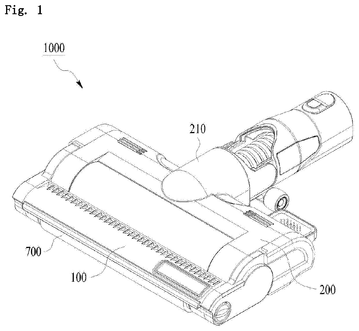
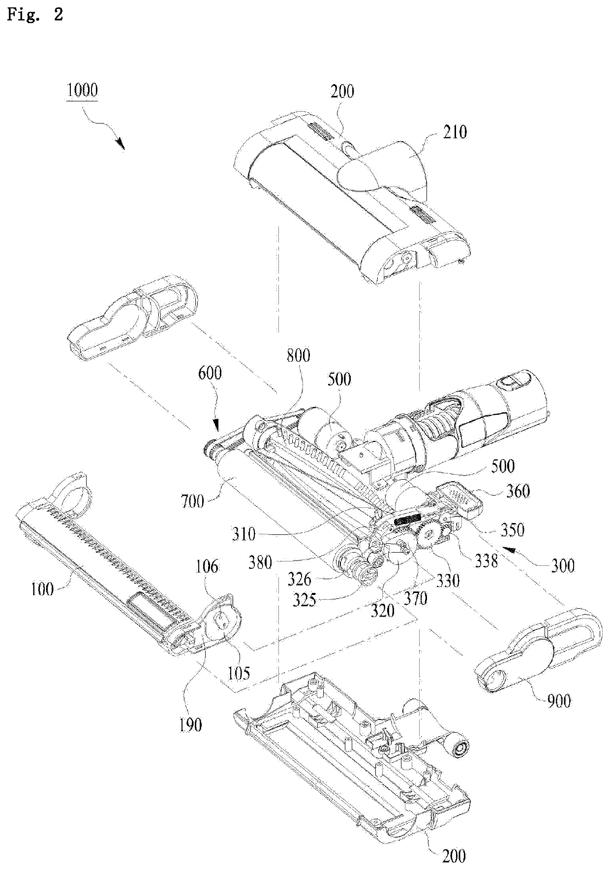
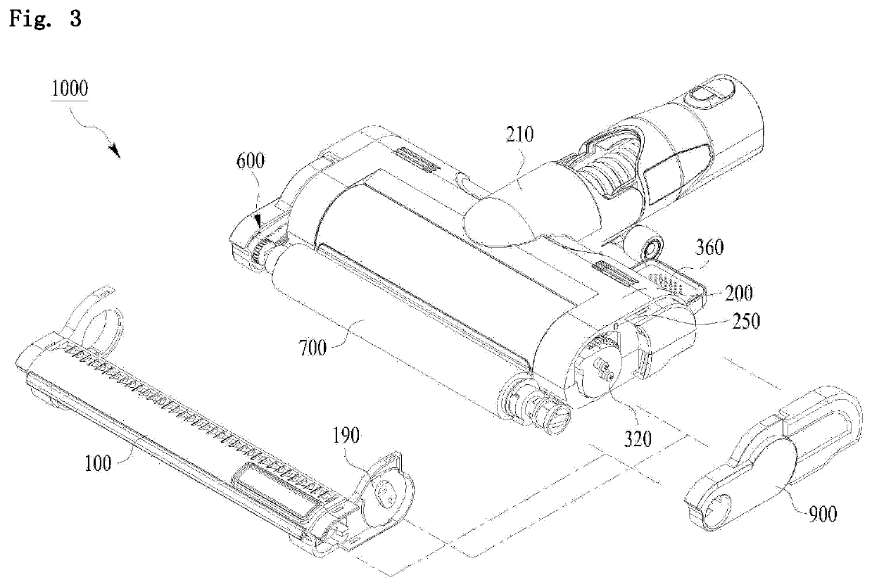
[0041]As shown in FIGS. 1 to 4, a cleaner head 1000 according to the present invention includes: a front housing 100 and a rear housing 200 disposed side by side on front and rear sides thereof respectively, the rear housing 200 having an air outlet 210 formed thereon; a front brush 700 rotatably disposed on the front housing 100 in such a manner as to be exposed from the underside of the front housing 100; a rear brush 800 rotatably disposed the rear housing 200 in such a manner as to be exposed from the underside of the rear housing 200; driving motors 500 built in the rear housing 200 to rotate the front brush 700 and the rear brush 800 through a power transmission mechanism 600; a lifting unit 300 disposed on one side of the rear housing 200 to move up and down the front housing 100 with respect to the rear housing 200 in a hinged...


PUM


Abstract

The present invention relates to a cleaner head including: a front housing and a rear housing disposed side by side on front and rear sides thereof respectively, the rear housing having an air outlet formed thereon; a front brush rotatably disposed on the front housing in such a manner as to be exposed from the underside of the front housing; a rear brush rotatably disposed the rear housing in such a manner as to be exposed from the underside of the rear housing; driving motors built in the rear housing to rotate the front brush and the rear brush through a power transmission mechanism; a lifting unit disposed on one side of the rear housing to move up and down the front housing with respect to the rear housing in a hinged manner; and a sensing part disposed on any one of the front housing and the rear housing and a part to be sensed disposed on the other, wherein when the front housing is stretched out with respect to the rear housing, rotating power is transferred to the front brush from the corresponding driving motor, and when the front housing is lifted, the rotating power transferred to the front brush cuts off to stop the rotation of the front brush.

Description

TECHNICAL FIELD[0001]The present invention relates to a cleaner head, and more particularly, to a cleaner head capable of lifting a front brush.REARGROUND ART[0002]Generally, a vacuum cleaner includes a body having a fan motor disposed at the inside thereof to generate a suction force, an extension tube at one end thereof connected to a suction port of the body, and a suction head disposed on the free end of the extension tube to suck foreign matters like dust through the suction force of the fan motor.[0003]Recently, a vacuum cleaner, which is configured to have a brush rotatably protruding from the underside of the suction head and a driving motor for driving the brush, has been popularly introduced.[0004]Further, a cleaner head, which is provided with two brushes having different characteristics disposed side by side in front and rear directions to provide a double brush structure, has been proposed, thereby enhancing agitation effects of foreign matters.[0005]In case of the conv...

Claims


Application Information

Patent Timeline
Patent Type & Authority Applications(United States)
IPC IPC(8): A47L9/04A47L9/28
CPCA47L9/0477A47L9/28A47L9/0433A47L9/0411A47L9/0494A47L9/2805A47L9/2847Y02B40/00A47L7/02A47L9/0405A47L9/0488A47L9/2857A47L9/2894
Inventor LEE, YOUNG MAN
Owner RAYCOP KOREA INC
Learn More