Monitoring device, monitoring system, monitoring method, and non-transitory storage medium

a monitoring device and non-transitory storage medium technology, applied in the direction of testing/monitoring control systems, instruments, heating types, etc., can solve the problems of failure, defect, and patent document 2 does not disclose a technique for detecting defects, so as to suppress unnecessary power consumption, reduce and suppress unnecessary increase the amount of power consumption of electrical devices

Inactive Publication Date: 2019-10-08
NEC CORP
View PDF15 Cites 0 Cited by
  • Summary
  • Abstract
  • Description
  • Claims
  • Application Information

AI Technical Summary

Benefits of technology

[0007]Methods of reducing the amount of power consumption may include (1) suppressing unnecessary power consumption due to an electrical device in a defective state by detecting the defect (such as a failure or an undesirable usage) of the electrical device during its operation at an early stage and appropriately coping with the defect, and (2) suppressing an unnecessary increase in the amount of power consumption of an electrical device by performing maintenance of an electrical device (for example, cleaning the filter of an air conditioner), and the like. In order to reduce the amount of power consumption using these methods, a technique for detecting a defect or unperformed maintenance of an electrical device is being demanded.

Problems solved by technology

The technique disclosed in Patent Document 1 allows detection of an abnormality in a process; however, there is a problem in that the technique is unable to detect a failure, a defect, and an abnormal state of which the details are not specified in advance.
Patent Document 2 does not disclose a technique for detecting a defect and unperformed maintenance of an electrical device.

Method used


Image

  • Monitoring device, monitoring system, monitoring method, and non-transitory storage medium
  • Monitoring device, monitoring system, monitoring method, and non-transitory storage medium
  • Monitoring device, monitoring system, monitoring method, and non-transitory storage medium

Examples


first exemplary embodiment

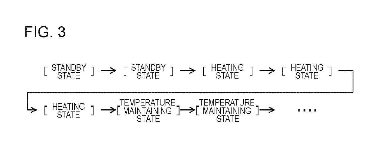
[0050]First, the outline of the present exemplary embodiment will be described. The inventors have examined electrical devices capable of assuming multiple types of operating states and have found that, “when there is no occurrence of a defect (such as a failure), a certain electrical device transitions between operating states in a predetermined pattern (standard pattern)”, and “when there is an occurrence of a defect (such as a failure), such an electrical device may exhibit a pattern of transition different from the standard pattern”. An example of such an electrical device may include an electric pot that heats a filled content such as water contained therein up to a predetermined temperature and maintains the content at a predetermined temperature.

[0051]The electric pot without the occurrence of a defect transitions from a standby state, which is a heating-start-instruction waiting state, to a heating state in which a filled content is heated, and then transitions to a temperat...

second exemplary embodiment

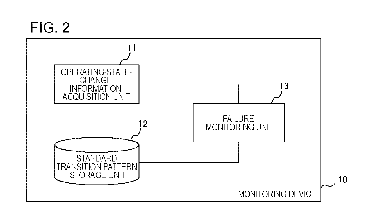
[0109]A monitoring device 10 of the present exemplary embodiment is different from that in the first exemplary embodiment, in that the device has a function of detecting an undesirable usage of an electrical device. An example of a functional block diagram of the monitoring device 10 of the present exemplary embodiment is shown in FIG. 2 or 22 similarly to the first exemplary embodiment. The configuration of the operating-state-change information acquisition unit 11 is the same as that in the first exemplary embodiment.

[0110]The standard transition pattern storage unit 12 stores the standard transition pattern information indicating a threshold of the frequency of occurrence of a standard transition, instead of or in addition to the standard transition pattern information described in the first exemplary embodiment.

[0111]This threshold indicates the upper limit of the standard transition appearing in a preferred usage. That is, if a standard transition is detected exceeding this thr...

third exemplary embodiment

[0117]A monitoring device 10 of the present exemplary embodiment has a function of outputting a determination result of a monitoring unit 13 and receiving an input of feedback information indicating whether the determination result is correct. The monitoring device 10 of the present exemplary embodiment has a function of correcting the determination standard of the monitoring unit 13 in accordance with the contents indicated by the feedback information.

[0118]FIG. 12 shows an example of a functional block diagram of the monitoring device 10 of the present exemplary embodiment. As shown in the drawing, the monitoring device 10 includes an operating-state-change information acquisition unit 11, a standard transition pattern storage unit 12, a monitoring unit 13, an output unit 14, an input receiving unit 15, and a correction unit 16. Meanwhile, similarly to the first and second exemplary embodiments, the monitoring device 10 may or may not include the standard transition pattern storag...


PUM


Abstract

In the present invention, provided is a monitoring device (10) including an operating-state-change information acquisition unit (11) that acquires operating-state-change information indicating a time-series change in operating states of an electrical device, the device being capable of assuming multiple types of operating states, a standard transition pattern storage unit (12) that stores standard transition pattern information indicating a pattern of transition between operating states generated in a normal electrical device, and a monitoring unit (13) that determines whether or not the electrical device is normal using the operating-state-change information and the standard transition pattern information.

Description

CROSS-REFERENCE TO RELATED PATENT APPLICATIONS[0001]This application is a National Stage Entry of International Application No. PCT / JP2014 / 080785, filed Nov. 20, 2014, which claims priority from Japanese Patent Application No. 2014-059753, filed Mar. 24, 2014. The entire contents of the above-referenced applications are expressly incorporated herein by reference.TECHNICAL FIELD[0002]The present invention relates to a monitoring device, a monitoring system, a monitoring method, and a program.BACKGROUND ART[0003]Patent Document 1 discloses a process management device that determines the presence or absence of abnormality by performing wavelet analysis on a plurality of pieces of process result data (such as, for example, energy consumption, outside air temperature, room temperature, and indoor humidity of air-conditioning equipment) obtained by measuring a process in a time-series manner, and transforming the analysis results into a three-dimensional contour pattern.[0004]Patent Docum...

Claims


Application Information

Patent Timeline
Patent Type & Authority Patents(United States)
IPC IPC(8): F24F11/00A47J27/21G01M99/00F24F11/64G05B23/02H04Q9/00F24F11/30F24F11/52F24F11/32
CPCF24F11/30A47J27/21091G01M99/008F24F11/64G05B23/0232H04Q9/00F24F11/52H04Q2209/823F24F2221/22F24F11/32F24F11/46F24F11/523
Inventor ITAYA, SATOKOLUO, YUANNAKAMURA, SHINMARUHASHI, KENICHI
Owner NEC CORP
Why Eureka
Try Eureka