Multifocal scanning fluorescence microscope

a fluorescence microscope and scanning fluorescence technology, applied in the field of scanning fluorescence microscopes, can solve the problems of increasing the loading of the sample, bleaching the sample, and the disadvantages of the sequence image composition

Active Publication Date: 2020-10-13
CARL ZEISS MICROSCOPY GMBH +1
View PDF13 Cites 1 Cited by
  • Summary
  • Abstract
  • Description
  • Claims
  • Application Information

AI Technical Summary

Benefits of technology

[0014]The distance-dependent, color-independent splitting of the light from the different (primary and secondary) focal planes also allows out-of-focal fluorescence to be imaged and simultaneously detected quasi-confocally. This reduces the sample loading, in that the input excitation light is better utilized. In particular, even for a number of measurement points, only a single illumination volume, and consequently also only a single upstream cone, need be excited.
[0042]The fluorescence excitation may take place both linearly (by means of single-photon excitation) and non-linearly (by means of multi-photon excitation or frequency multiplication—“Second Harmonic Generation” (SHG), CARS etc.). However, the detection in this case expediently takes place “descanned”. The particular advantage of non-linear excitation is that, as a result of the squaring of the intensity, it is easier to generate an axially extended PSF. Furthermore, the method can also be combined with other methods of fluorescence imaging, for example with “Focal Modulation Microscopy” (Chen et al. in “Optics Express”, volume 16, edition 23, page 18764).

Problems solved by technology

However, scanning, sequential image composition also has disadvantages.
A further problem is the bleaching of the sample.
However, this leads to increased loading of the sample, and as a consequence to strong bleaching and photographic damage.
As a result, this microscope is only suitable for monochromatic imaging.

Method used


Image

  • Multifocal scanning fluorescence microscope
  • Multifocal scanning fluorescence microscope
  • Multifocal scanning fluorescence microscope

Examples


Embodiment Construction

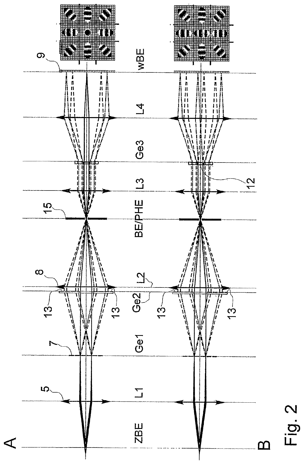
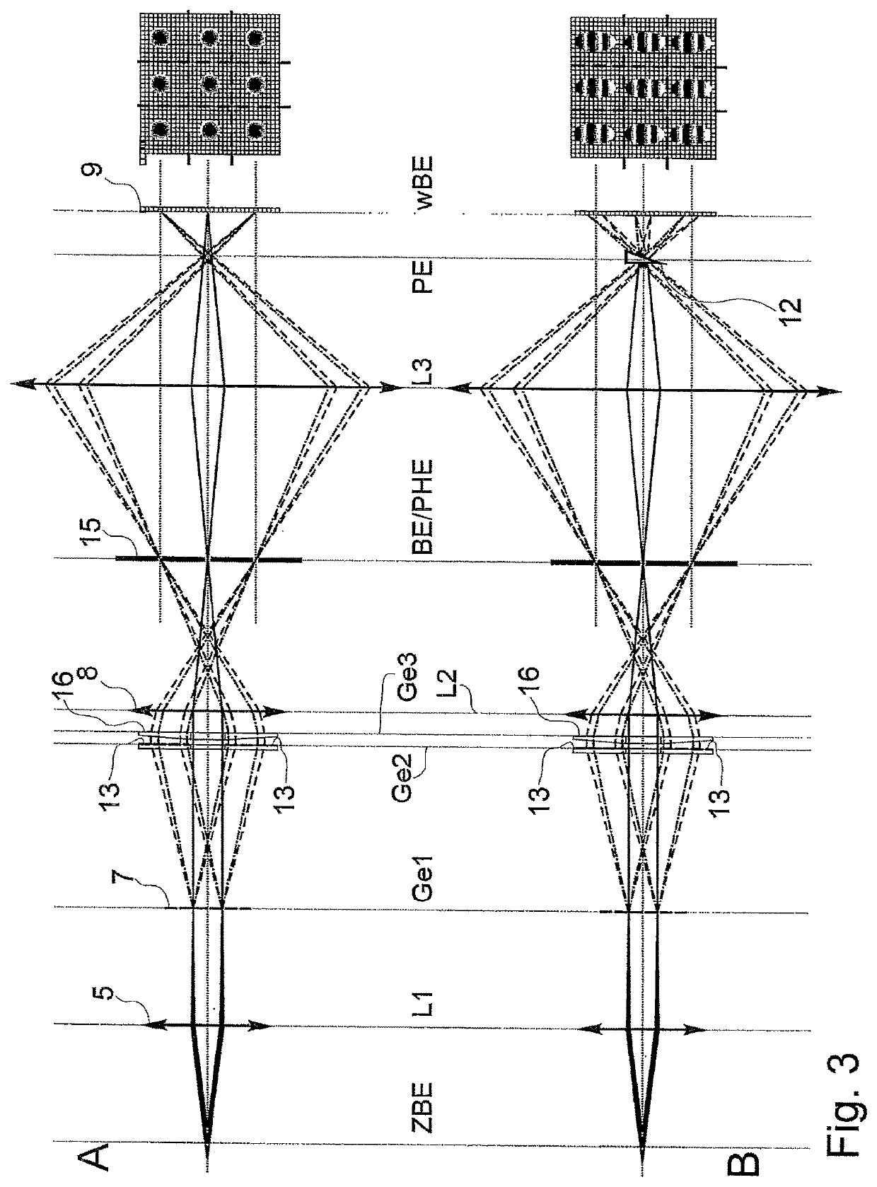
[0049]In all of the drawings, parts that coincide bear the same reference signs.

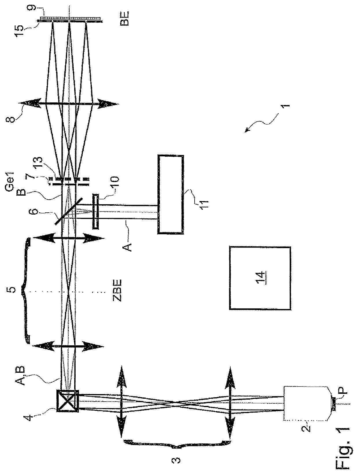
[0050]FIG. 1 schematically shows a scanning fluorescence microscope 1 in the form of a laser scanning microscope (LSM). Here, a laser as a light source 11 as an illumination system together with a microscope objective 2 defines an illumination beam path A, which contains a phase mask 10 and is combined (optically coupled) by a beam splitter 6, for example a dichroic beam splitter cube, with the observation beam path B. The phase mask 10 is arranged outside the observation beam path B. An optical transfer system 5 images the plane of the phase mask 10 onto a deflecting unit 4, which can deflect the excitation light beam in the x and y directions. A further optical transfer system 3 images the deflecting unit 4 into the pupil plane of the objective 2. The objective 2 focuses the laser beam into the sample P, the lateral position of the illumination volume depending on the deflecting angles that are set on ...


PUM


Abstract

Scanning fluorescence microscopes with an observation beam path from a measurement volume to an image plane. A beam combiner is provided for coupling an illumination system and a diaphragm arranged in the image plane for slow composition of the image because of the sequential scanning and subject the sample to loading as a result of inefficient use of the excitation light. The microscope simultaneously detects fluorescence from different focal planes in each case quasi-confocally. The observation beam path between the beam combiner and the image plane has a first diffractive optics for splitting light beams into beam bundles along different orders of diffraction, imparting to the light beams a spherical phase that is different from the other orders of diffraction. A second diffractive optics is provided for the compensation of chromatic aberrations of the split beam bundles, and a collecting optics is provided for focusing split beam bundles into the image plane.

Description

RELATED APPLICATIONS[0001]The present application is a U.S. National Stage application of International PCT Application No. PCT / EP2015 / 052605 filed on Feb. 9, 2015 which claims priority benefit of German Application No. DE 10 2014 002 328.1 filed on Feb. 12, 2014, the contents of each are incorporated by reference in their entirety.FIELD OF THE INVENTION[0002]The invention relates to a scanning fluorescence microscope with an optical system, which defines a microscopic observation beam path from a measurement volume to an image plane and comprises (enumerated in the direction from the measurement volume to the image plane) a microscope objective, a beam combiner with an input for coupling an illumination system and a diaphragm arranged in the image plane. The diaphragm is referred to hereinafter as a confocal diaphragm. The microscope may expediently also comprise an illumination system with a light source, preferably at least one laser.BACKGROUND OF THE INVENTION[0003]Confocal scan...

Claims


Application Information

Patent Timeline
Patent Type & Authority Patents(United States)
IPC IPC(8): G02B21/00G02B27/00G02B27/10G02B27/42G02B21/36G02B27/09G02B21/33
CPCG02B27/0037G02B21/0076G02B21/33G02B27/4227G02B27/4211G02B27/0927G02B27/0988G02B21/367G02B21/0032G02B21/0064G02B27/1086G02B27/0075G02B21/004
Inventor ANHUT, TIEMOSCHWEDT, DANIELWALD, MATTHIAS
Owner CARL ZEISS MICROSCOPY GMBH
Why Eureka
Try Eureka