Pneumatic reciprocating saw

a reciprocating saw and pneumatic technology, applied in the field of pneumatic reciprocating saws, can solve the problems of inability to hold the pneumatic reciprocating saw for a long time, inability to perform good cutting operation, and inability to achieve good cutting operation. the effect of preventing overheating and moving more stably

Active Publication Date: 2020-10-20
DIN LONG IND
View PDF8 Cites 1 Cited by
  • Summary
  • Abstract
  • Description
  • Claims
  • Application Information

AI Technical Summary

Benefits of technology

The present invention solves the problem of the conventional driven piece having only one supporting point and being prone to deviation during use. The invention includes a thermal insulator that is sleeved on the transmission rod and contacts the housing. This insulator prevents the housing from overheating and ensures stable movement of the saw blade during use. The invention also provides additional support for the transmission rod through the thermal insulator, resulting in a more stable and accurate movement of the saw blade.

Problems solved by technology

However, many parts are required for this patent, so that rapid assembly is not facilitated, and more attention needs to be paid to the assembly relationship between components during assembly, so that the pneumatic reciprocating saw is complicated and time-consuming to assemble.
The applicant has found that when the pneumatic reciprocating saw disclosed as mentioned above is implemented, because the transmission assembly thereof operates for a long time, each element of the transmission assemblies generates heat energy due to friction therebetween, and the heat is also conducted to the housing of the pneumatic reciprocating saw at the same time, so that the housing of the pneumatic reciprocating saw is heat up, and a user cannot hold the pneumatic reciprocating saw for a long time.
In addition, since the driven piece of the conventional pneumatic reciprocating saw is only provided with a single supporting point after being assembled, the driven piece is easy to deviate during implementation, and the pneumatic reciprocating saw cannot perform good cutting operation.

Method used


Image

  • Pneumatic reciprocating saw
  • Pneumatic reciprocating saw
  • Pneumatic reciprocating saw

Examples


Embodiment Construction

[0027]The detailed description and technical contents of the present invention will now be described with reference to the drawings as follows:

[0028]Hereinafter, the terms “first” and “second” used with respect to elements are intended to distinguish the elements and are not intended to limit the order of the elements. Further, as used herein, spatial relative terms such as “top”, “bottom”, “up”, “down” and the like are based on the orientation depicted in the figures herein, and it is to be understood that the spatial relative terms may vary with the change of the orientation depicted in the figures. For example, after FIG. 1 is disposed transversely, the previous “top” and “bottom” will vary to “left” and “right”, respectively.

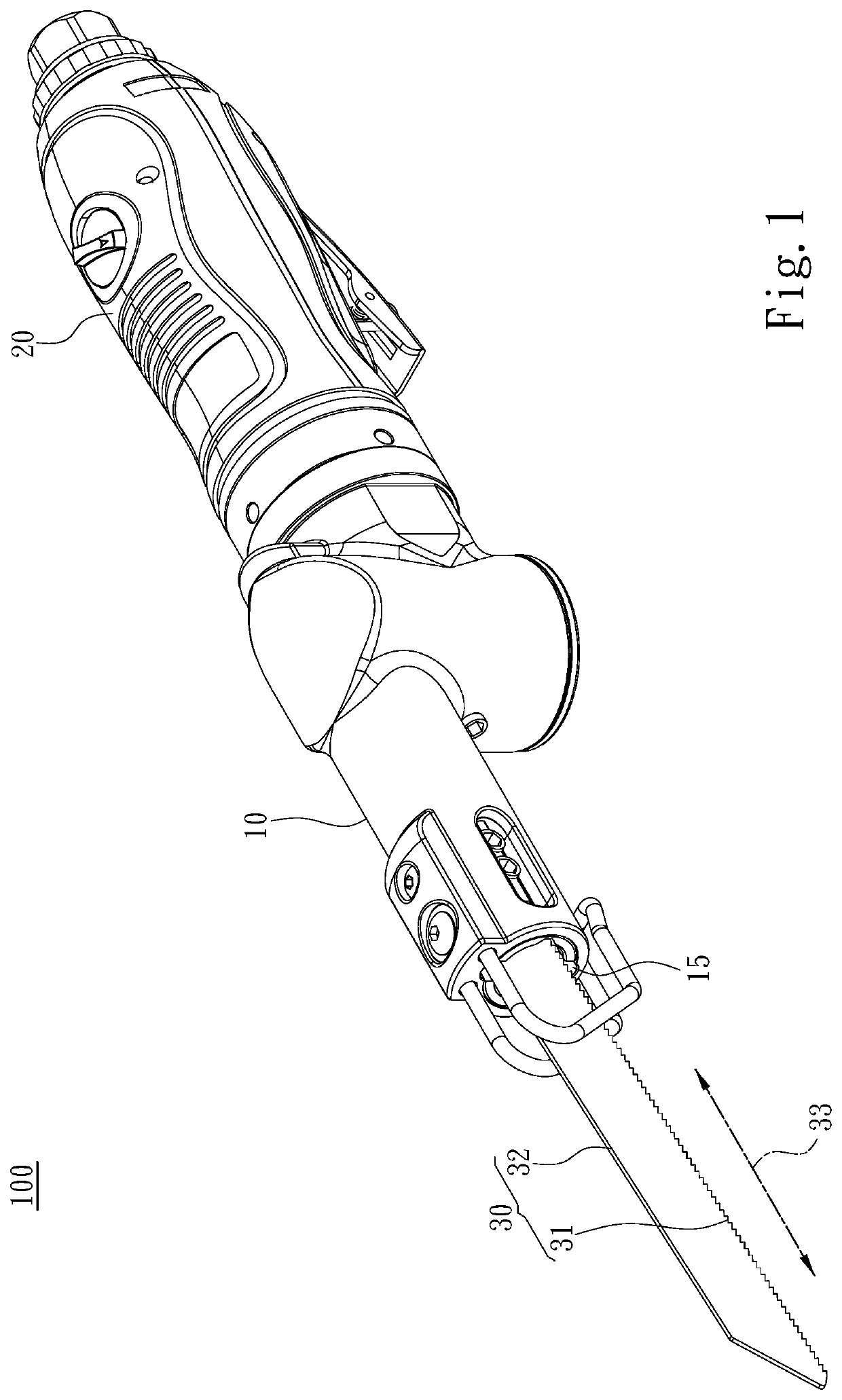
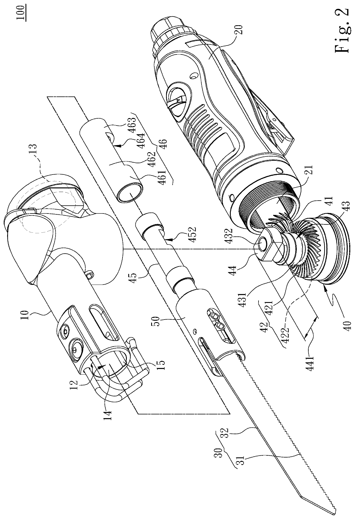
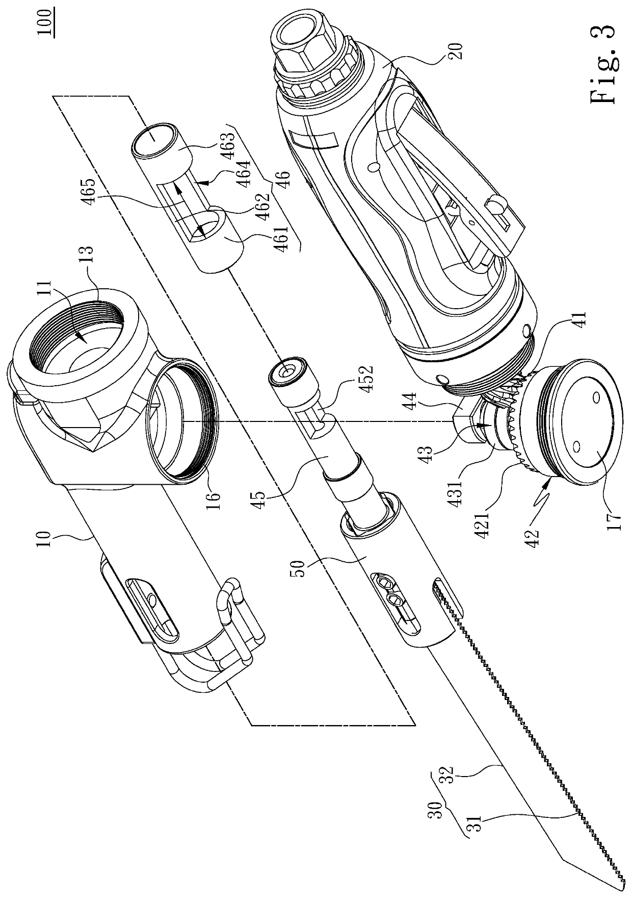
[0029]Referring to FIGS. 1, 2, 3, 4A and 4B, the present invention provides a pneumatic reciprocating saw 100 comprising a housing 10, a pneumatic motor 20, a saw 30, and a transmission assembly 40. The housing 10 is formed with a first assembly space 11, a ...


PUM

PropertyMeasurementUnit
Diameteraaaaaaaaaa
Lengthaaaaaaaaaa
Thermal insulatoraaaaaaaaaa

Abstract

A pneumatic reciprocating saw comprises a housing, a saw extending into the housing, a pneumatic motor assembled with the housing and a transmission assembly. The pneumatic motor comprises an output shaft, the transmission assembly comprises a driving bevel gear arranged on the output shaft, a transmission bevel gear engaged with the driving bevel gear, a driven rod being arranged on the transmission bevel gear, a pushing block being eccentrically arranged on the driven rod, a transmission rod assembled with the saw, and a thermal insulator sleeved on the transmission rod without being shifting along with the transmission rod. The transmission rod comprises a groove for placing the pushing block to slide therein, when the transmission rod is driven to reciprocate in a linear track, a tail end of the transmission rod not connected with the saw being limited by the thermal insulator to only move in the linear track.

Description

FIELD OF THE INVENTION[0001]The invention relates to a pneumatic reciprocating saw, in particular to a pneumatic reciprocating saw with a heat insulation effect.BACKGROUND OF THE INVENTION[0002]The existing pneumatic reciprocating saw mainly utilizes a high pressured air as a power source to drive a pneumatic motor to drive a transmission assembly, so that a blade of the existing pneumatic reciprocating saw can perform reciprocating shift to cut objects to be cut. Further, for the structure of the conventional pneumatic reciprocating saw can be refer to the patent of U.S. Pat. No. 8,646,185.[0003]U.S. Pat. No. 8,646,185 discloses a pneumatic reciprocating saw comprising a driving machine, a machine body and a cutter. The driving machine have a driving shaft and a trigger, the driving shaft is rotatably arranged in the driving machine with one end protruding outside the driving machine and a gear part is arranged at an end of the driving shaft, the driving shaft is interconnected wit...

Claims


Application Information

Patent Timeline
IPC IPC(8): B23D49/00B23D49/16B23D51/18
CPCB23D51/18B23D49/00B23D49/162
Inventor HSIEH, JUNG-FU
Owner DIN LONG IND
Why Eureka
Try Eureka