Mooring system and method for power generation systems and other payloads in water flows

a power generation system and mooring system technology, applied in the field of new concept of mooring system and method, can solve the problems of high cost involved in marine construction, difficulty in harnessing the power of ocean current, practical and cost-effective system, etc., and achieves easy transportation, easing depth problems, and extended lateral displacement (or horizontal displacement) capacity.

Active Publication Date: 2020-10-20
NATIONAL TSING HUA UNIVERSITY
View PDF36 Cites 1 Cited by
  • Summary
  • Abstract
  • Description
  • Claims
  • Application Information

AI Technical Summary

Benefits of technology

[0009]In response to the issues and needs mentioned above, a new concept of Cross-stream Active Mooring (CSAM) of turbine generators for harvesting ocean current energy is devised in this invention. The system includes a mooring mechanism that can deploy turbine generators cross-stream to access the fast currents off anchoring points and maximize energy capture. The system can actively adjust vertical depth as well as horizontal positions to dodge rough sea conditions in storms and to accommodate current track variations. The system also includes new anchoring designs that can provide improved capacity at affordable costs. In accordance with one objective of the present disclosure, a mooring system for capable of deploying a payload (for example, a power generation turbine for harnessing kinetic power of flowing water) in a fluid moving relative to the payload and placing the payload to a target position laterally (in horizontal direction) across moving path of the fluid from an anchoring point is devised. The mooring system comprises: a main tether; an anchor means attached to a first end of the main tether and fixed to the anchoring point; and a main sail means attached to a second end of the main tether and immersed in the fluid. The payload is attached to the second end of the main tether. When the moving fluid flows over the main sail means a fluid dynamic lift force is created on the main sail means and the main sail means pulls the payload in a lateral direction with respect to the moving path of the fluid, that is, horizontally, away from the anchoring point. The mooring system can therefore place the payload to the target position horizontally across moving path of the fluid from an anchoring point.
[0010]Preferably, the main sail means may further comprise a lift adjusting means capable of causing changes of magnitude of the fluid dynamic lift force and thereby changing position of the payload laterally with respect to the anchoring point.

Problems solved by technology

However, harnessing the power of ocean current faces many difficulties.
Despite the great potential of ocean current power generation, the realization of a practical and cost-effective system faces several major difficulties.
One major issue is the potentially high cost involved in marine construction due to depth of seafloors.
However, these ridges are likely of hard andesite and have almost no sediments on their top surfaces.
As a result, embedment anchors are not likely to be applicable and piling at this depth will be very expensive.
Anchoring difficulties aside, the comparatively shallow hill tops in the undersea ridges have limited areas.
This limited footprint cannot moor the large number of turbines needed for a mass scale power system if traditional downstream mooring methods are used.
However, anchoring in this area may face a different problem: the axis of the high speed core is actually outside of the areas identified as suitable for anchoring, due to wide presence of corals and deep reefs. FIG. 41 shows averaged tracks of the Florida Current over topographic map of the Florida Straits marked with seafloor characteristics.
Another issue is the variation of the tracks of current velocity cores (or called meandering), which can impact the efficiency of an ocean current power system.
In Japan, the issue of the “large meander” of the Kuroshio is especially serious.
A capacity factor of 0.8-0.9 in annual terms is high for a fluid kinetic power system, but occasional power outage for over a full year is not acceptable for any large scale investment.
Therefore, this is a very serious issue for potential power generation in the Kuroshio south of Japan.
Ocean eddies and typhoons could also cause short term change of current flow direction undersea.
Still another issue, also associated with geographical locations, is that typhoons or hurricanes occur frequently in these waters.
Individual anchoring may be normal for tidal power in shallow waters but will be very expensive for deep sea floating systems.
A large number of individual anchoring points distributed over large areas on deep seafloors means complexity of marine constructions and long duration of works.
As a result, seafloor area usage will be inefficient and gravity anchors, if used, will also be inefficient due to short anchor lines.
The use of individual and short mooring lines means that the generator systems will basically be fixed location systems, unable to make adequate position adjustments to accommodate small, short term change of ocean current path let alone the situation of large meanders.
As for Kiryu's “energy boats” concept, the use of surface floating power vessels has system stability issues compared to submerged floating system, especially in storms, and cost issues as well.

Method used


Image

  • Mooring system and method for power generation systems and other payloads in water flows
  • Mooring system and method for power generation systems and other payloads in water flows
  • Mooring system and method for power generation systems and other payloads in water flows

Examples


Embodiment Construction

[0080]In the following description, specific details are presented to provide a thorough understanding of the embodiments of the present disclosure. Persons of ordinary skill in the art will recognize, however, that the present disclosure can be practiced without one or more of the specific details, or in combination with other components. Well-known implementations or operations are not shown or described in detail to avoid obscuring aspects of various embodiments of the present disclosure.

[0081]Basic Analytical Model

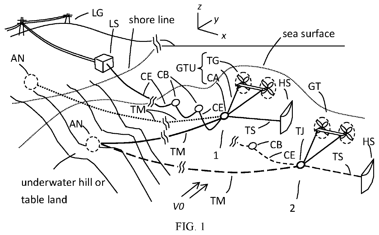
[0082]In accordance with an exemplary embodiment of the present disclosure, FIG. 1 illustrates the basic concept of the Cross-stream Active Mooring (CSAM) in perspective view. The mooring system comprises a main tether TM, an anchoring point AN at one end of the main tether TM and a hydro sail HS attached to the other end. The hydro sail HS is basically a wing (or sail) profile with its span oriented roughly in vertical direction. The hydro sail HS and most of the main...


PUM


Abstract

A mooring system for deploying flow kinetic power generation systems in a water flow and placing the power generation systems to a position across moving path of the water flow from an anchoring point, the mooring system comprises: a main tether; an anchor means attached to a first end of the main tether and fixed to the anchoring point; and a main sail means attached to a second end of the main tether and immersed in the water flow; wherein the power generation systems is attached to the second end of the main tether; and the relative to the main sail means creates a fluid dynamic lift force on the main sail means and pulls the power generation systems in a lateral direction with respect to the moving path of the water flow. The mooring system may also be applied to moor and deploy other payloads and devices transversely across a water flow.

Description

CROSS-REFERENCE TO RELATED APPLICATION[0001]This application is a non-provisional of U.S. provisional Application No. 62 / 410,881 filed in the United States Patent and Trademark Office on Oct. 21, 2016, the disclosure of which is incorporated by reference herein in its entirety.BACKGROUND OF THE INVENTION1. Field of the Invention[0002]The present disclosure relates to a new concept of a mooring system and method thereof, especially for mooring and anchoring of power generation systems that harnessing kinetic power of water flows.2. Description of the Related Art[0003]The kinetic power of a body of fluid of density ρ flowing through a cross sectional area A at speed V isP=ρ[(AV)] 3 / 2[0004]Flow speeds in the Kuroshio and the Gulf Stream can be over 1-2 m / s. The cross-sectional power of the Kuroshio fluctuates between 4 to 10 GW with an annual mean around 6 GW and that of the Gulf Stream varies between 5 to 25 GW with an annual mean of about 12 GW. However, harnessing the power of ocean...

Claims


Application Information

Patent Timeline
Patent Type & Authority Patents(United States)
IPC IPC(8): B63B21/50H02K7/18F03B17/06B63G8/00
CPCB63B21/50F03B17/06H02K7/1823Y02E10/20F05B2240/95F05B2240/917F05B2240/40Y02E10/30B63G8/001F05B2240/9174
Inventor TSAO, CHE-CHIH
Owner NATIONAL TSING HUA UNIVERSITY
Why Eureka
Try Eureka