Device for filling a tube with particulate filling material

a technology of filling material and tube, applied in the direction of loading/unloading, chemical/physical processes, chemical apparatus and processes, etc., can solve the problems of catalyst mass absorption, unfavorable pressure loss, particle breakage, etc., to reduce the filling rate, the effect of preventing clogging and slowing down the filling ra

Active Publication Date: 2020-11-03
COTA ALDO
View PDF14 Cites 0 Cited by
  • Summary
  • Abstract
  • Description
  • Claims
  • Application Information

AI Technical Summary

Benefits of technology

[0012]It was possible to achieve the above object in particular by providing an improved filling device which not only has the fall arrester elements comprising a net structure that are known from EP-A-1 749 568, but also additionally has specially designed filling-material deflectors above each fall arrester element.
[0013]These filling-material deflectors are configured such that they protect the central region, which is subjected to the greatest mechanical load, of a fall arrester element, or the central region of the corresponding net structure, and in particular the inner portion of the individual net elements, via which the latter are fastened to the body of the fall arrester element, from being struck directly by filling-material particles, but, on the other hand, do not significantly slow down the filling rate or even cause clogging of the tubular reactor with filling material during the filling operation.
[0014]The falling speed of the filling material is, according to the invention, effectively reduced and, moreover, in the configuration according to the invention of the device, even at a high filling rate, clogging of the tube to be filled does not occur. Surprisingly, it has been found that when a loose, flexible and irregular net structure made up of one or more flexible, curved net elements in combination with such filling-material deflectors is used, fault-freer and gentle filling of a tube with particulate filling material becomes possible. Specifically, according to the invention, it has in particular been observed that, as a result of the configuration according to the invention of the fall arrester element in combination with a central filling-material deflector arranged thereabove, the filling-material particles are distributed, or scattered, quickly over the tube cross section during the filling operation, clogging is effectively prevented by this relatively disordered movement, and at the same time the net elements, or fall arrester elements have a greatly improved service life.

Problems solved by technology

When the catalyst particles, which are frequently very sensitive mechanically, are poured in, particles can break up on account of excessive mechanical force application or catalyst mass can be abraded.
As a result, the catalyst filling is compacted and causes undesired pressure losses when the reactor is operated.
In the case of nonuniform filling, there is also the risk of the formation of what are known as “hot spots”, i.e. zones of undesirably high temperature in the reactor, which impair the control of the reaction process.
This device known from the prior art has serious drawbacks in practice.
In particular, the radial arrangement of the straight, short bristles of the arresting means frequently causes undesired faults during the filling operation.
As a result, clogging of the tube frequently occurs and, as a result, tearing of the carrier cable.
In order to remedy this fault, the filling operation has to be interrupted and catalyst that has already been poured in sucked out again, with the result that the entire operation is unnecessarily retarded and the downtime of the plant is unnecessarily extended.
If the filling operation is not carried out continuously, this can also impair the homogeneity of the particle bed.
Overall, in such a device, the handling of the filling tube during filling is particularly awkward and furthermore the filling operation is slowed down unnecessarily thereby.
In any case, however, the production of such additional grating elements is complicated and expensive and, furthermore, the elasticity of such arrester elements is undesirably reduced overall as a result.
However, no design details whatsoever are provided.
A drawback here is that the device can be set into violent rotary motion during filling, with the result that coverage of the tube cross section with arrester elements is no longer reliably ensured and thus fall arresting is not optimal.
Homogeneous formation of the deposited catalyst bed therefore cannot be achieved, and at a higher filling rate there is also the risk of the catalyst particles breaking up and thus “hot spots” forming during plant operation.
Therefore, the net structure is exposed to strong mechanical loads in the central region during filling.
The strong mechanical loading when such particles strike individual net elements results in this case in increased material fatigue and in the breaking of individual net elements.
Premature replacement of individual entire fall arrester elements and possibly even a relatively long interruption to the filling operation may therefore be necessary.

Method used


Image

  • Device for filling a tube with particulate filling material
  • Device for filling a tube with particulate filling material
  • Device for filling a tube with particulate filling material

Examples


Embodiment Construction

a) General Definitions

[0029]A net structure is “permeable” within the meaning of the invention when the filling-material particles do not pass through the net structure in an unimpeded manner during the filling of the tube but come into contact with at least one net element of the net structure and in this way have their falling speed reduced.

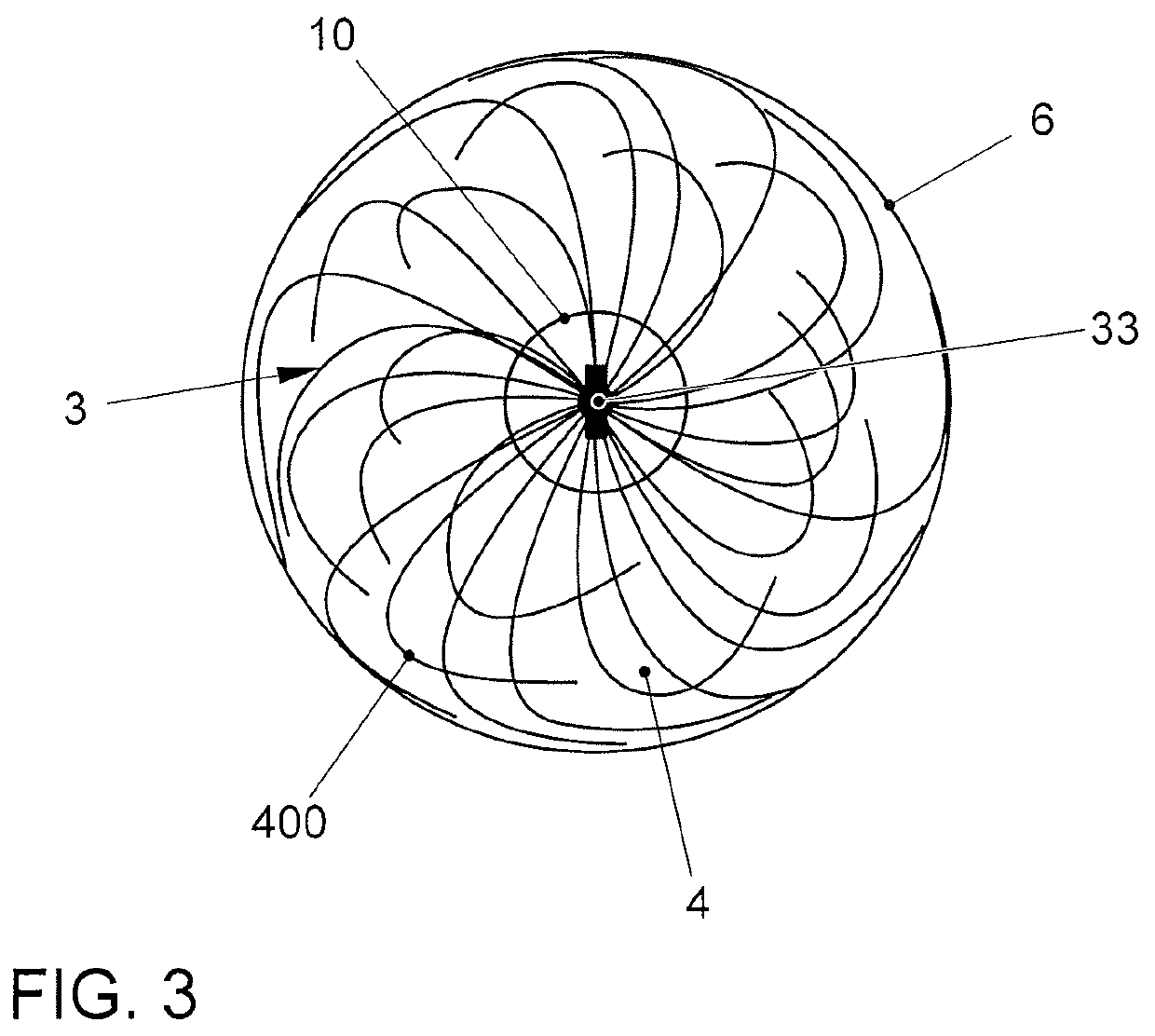
[0030]A “net structure” within the meaning of the invention should be understood as being a radial “open” or “closed” arrangement of individual, at least one (for example a metal-wire thread that is formable into individual loops), in particular at least two net elements (for example loops, zigzag fibers, curved fibers or combinations thereof) on the fall arrester element. Furthermore, a net structure according to the invention is distinguished by the fact that, in its vertical projection, i.e. in plan view of the fall arrester element(s) (or in the filling device extending along the longitudinal axis of the tube), individual, in particular at ...


PUM

PropertyMeasurementUnit
diametersaaaaaaaaaa
angleaaaaaaaaaa
angleaaaaaaaaaa

Abstract

A device for gently and uniformly filling a tube, in particular a tubular reactor, with particulate filling material, in particular catalyst particles; wherein the device includes specially designed fall arrester elements and also comprises deflectors that reduce the wear of the fall arrester elements. Another aspect of the invention provides a method for filling a tube using these articles.

Description

CROSS-REFERENCE TO RELATED APPLICATIONS[0001]This application is the U.S. national phase, pursuant to 35 U.S.C. § 371, of PCT international application Ser. No. PCT / EP2017 / 051671, Jan. 26, 2017, designating the United States and published in German on Aug. 3, 2017 as publication WO 2017 / 129689 A1, which claims priority under 35 U.S.C. § 119(a) to European patent application No. 16153078.7, filed Jan. 28, 2016. The entire disclosures of the aforementioned patent applications are hereby incorporated herein by reference.[0002]The present invention relates to a device for gently and uniformly filling a tube, in particular a tubular reactor, with particulate filling material, in particular catalyst particles; wherein the device comprises specially designed fall arrester elements and also comprises means which reduce the wear of the fall arrester elements; and method for filling a tube using these articles.BACKGROUND OF THE INVENTION[0003]For carrying out chemical reactions in tubular rea...

Claims


Application Information

Patent Timeline
Patent Type & Authority Patents(United States)
IPC IPC(8): B01J8/00B01J8/06B65G69/16
CPCB01J8/0045B65G69/16B01J8/06B01J8/002B01J8/003B01J2208/00778B01J2208/00752B01J2208/00769B01J2208/06
Inventor COTA, ALDO
Owner COTA ALDO
Why Eureka
Try Eureka