Anti-cavitation restrictors for injector control valves

A technology for controlling valves and valve seats, which is applied in fuel injection control, engine control, fuel injection pumps, etc., and can solve problems such as reduction and bubble generation

Active Publication Date: 2019-04-23
STANADYNE OPERATIONS LLC
View PDF7 Cites 0 Cited by
  • Summary
  • Abstract
  • Description
  • Claims
  • Application Information

AI Technical Summary

Problems solved by technology

When the control valve opens, the upstream fluid pressure drops rapidly, causing air bubbles to develop

Method used


Image

  • Anti-cavitation restrictors for injector control valves
  • Anti-cavitation restrictors for injector control valves
  • Anti-cavitation restrictors for injector control valves

Examples


Embodiment Construction

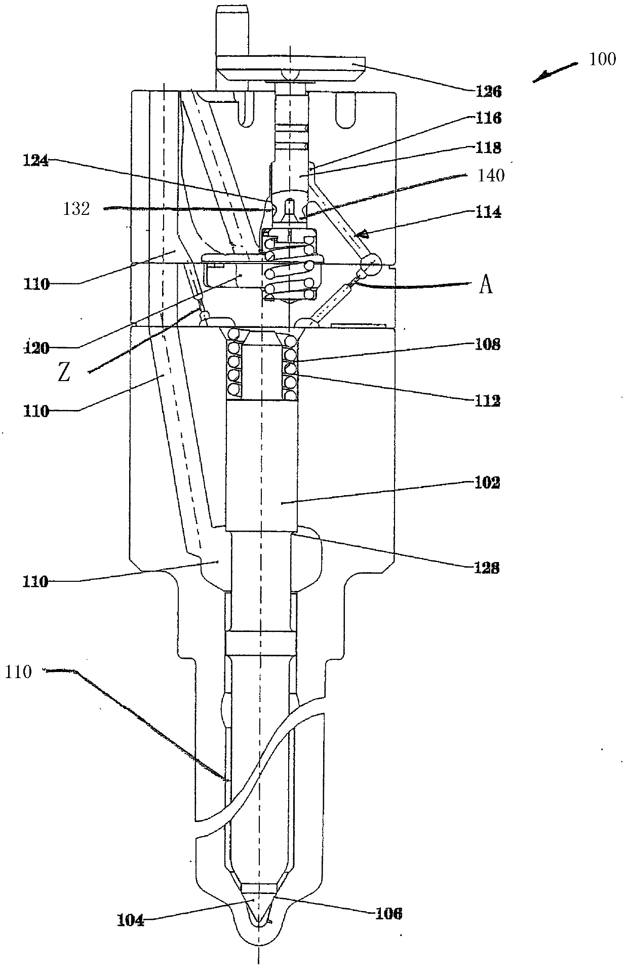
[0025] figure 1 with 2 An embodiment of the injector 100 having a needle valve 102 is shown. The needle valve 102 has a tip 104 that engages a seat 106 in the injector body under closed conditions during the injection event. In this closed condition, the needle control chamber 108 is supplied with high-pressure fuel 110 from a high-pressure feed pump (not shown), and similarly, the same high-pressure fuel 110 is supplied to the annular surface 128 at the middle position on the needle. . Due to the difference in area, the fluid pressure on the injection needle at the control chamber 108 is significantly higher than the fluid pressure at the upper end of the needle. Since this net downward fluid force is counteracted by the spring 112 in the chamber 108, the needle is maintained against the support 106.

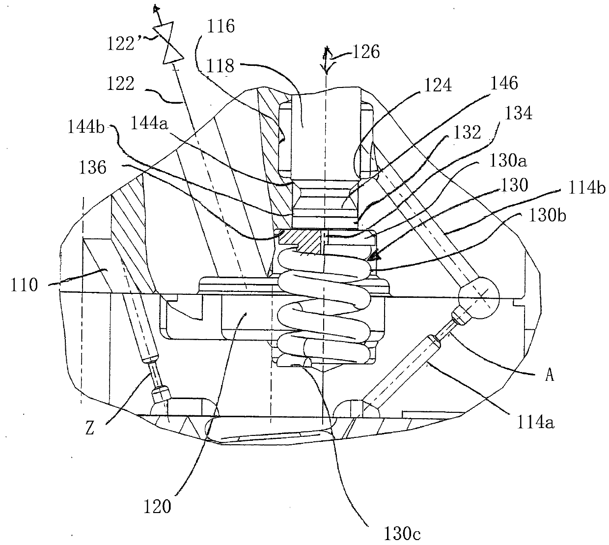
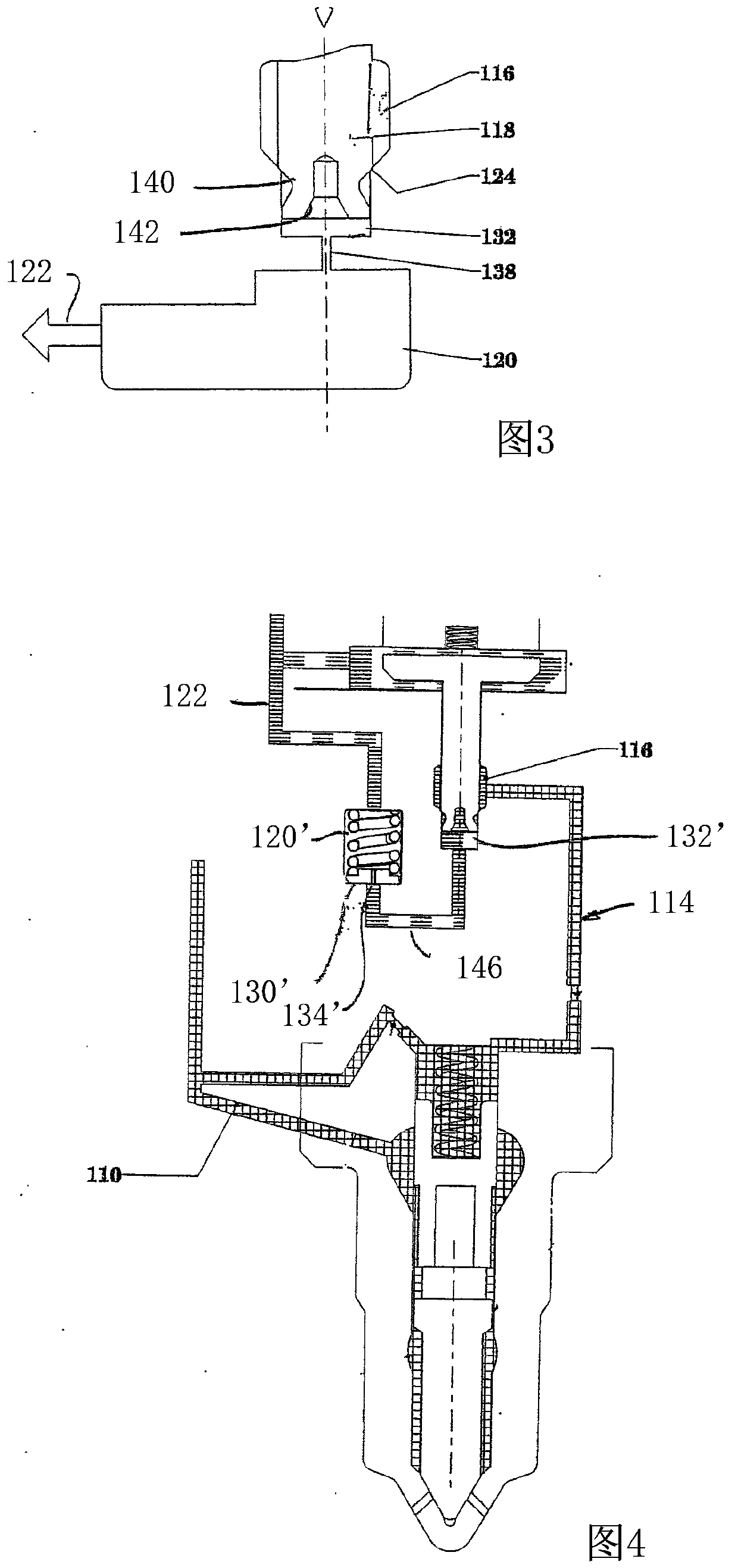
[0026] The flow passages 114 a and b connect the high-pressure needle control chamber 108 and the control valve chamber 116. The control valve 118 has a shank pin with a general...


PUM


Abstract

A needle-type fuel injector having a needle control chamber in which the control valve is subjected to pressure and whose control valve is lifted off its seat during the opening phase to place the control valve chamber, connecting flow passage and needle The control chamber is exposed to the low pressure drain and during the closing phase it is pushed against the seat to isolate the control valve chamber, connecting flow channel and needle control chamber from the drain. The potential for cavitation at high fuel injection pressures is reduced by throttling fuel flow past the control valve seat when the control valve is open thereby maintaining sufficient back pressure in the control valve chamber and upstream connecting flow passages.

Description

Technical field [0001] The present invention relates to a diesel engine fuel injector, in which the pressure in a solenoid valve control chamber acts on a needle injection valve. Background technique [0002] In these types of injectors, the control valve acts as a normally closed valve in the control chamber to separate the fuel in the needle control chamber from the low pressure zone and the associated flow path under high pressure. A spring or similar component on the solenoid armature or shaft causes a shaped pin or similar component to push against a correspondingly shaped control room support. The injection event begins with the solenoid being energized, which lifts the control valve away from the seat so that the high-pressure fuel in the needle control chamber communicates with the flow path leading to the low-pressure area or tank, and the injector pointer is lifted in a known manner Abutment away from the bottom of the ejector body. The raised needle exposes the injec...

Claims


Application Information

Patent Timeline
Patent Type & Authority Patents(China)
IPC IPC(8): F02D1/00
CPCF02M63/0005F02M61/10F02M2200/28F02M2200/04F02M61/12F02M47/027F02M63/0056
Inventor M·S·卡瓦纳
Owner STANADYNE OPERATIONS LLC
Why Eureka
Try Eureka