Suspension bush and suspension device
a suspension device and suspension bush technology, applied in the direction of sliding contact bearings, mechanical devices, transportation and packaging, etc., can solve the problems of more difficult to change the toe angle toward the inside of the turn, and impaired handling of the vehicle, so as to achieve excellent handling and stability of the vehicle, excellent handling and stability
- Summary
- Abstract
- Description
- Claims
- Application Information
AI Technical Summary
Benefits of technology
Problems solved by technology
Method used
Image

Examples
first embodiment
2.3 Conclusion of First Embodiment
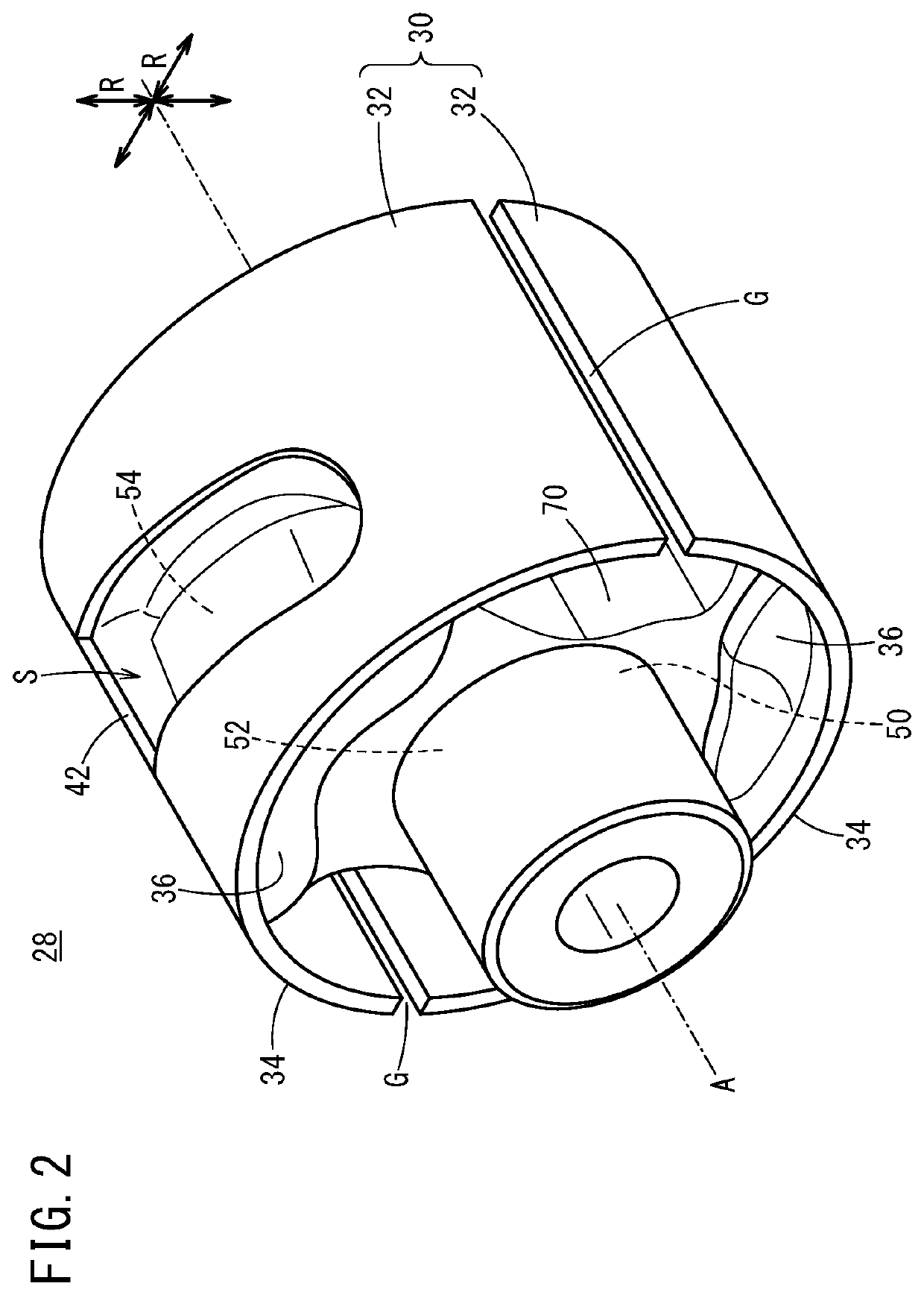
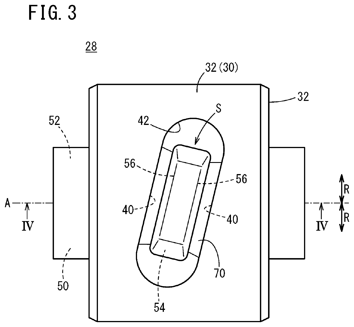
[0055]The suspension bush 28 according to the first embodiment includes the inner cylinder 50 and the outer cylinder 30 aligned with each other on the identical axis A and the elastic member 70 lying between the inner cylinder 50 and the outer cylinder 30. The inner cylinder 50 includes the projections 54 formed on the outer circumference thereof. The outer cylinder 30 includes the guides 36 formed on the inner circumference thereof. As illustrated in FIG. 5, each of the guides 36 has the slit 38 formed therein in the drawing direction D1 including the component CP1 in the parallel directions P1 parallel to the axis A and the component CR1 in the circumferential directions R1 about the axis A. The projections 54 are disposed in the slits 38, and the projections 54 and the slits 38 forming a screw mechanism.
[0056]In the above-described structure, in the case where the external force F1 in the parallel directions P1 parallel to the axis A acts on the ...
first embodiment and second embodiment
3.2 Comparison Between First Embodiment and Second Embodiment
[0067]The suspension bush 28 according to the second embodiment operates in a manner similar to the suspension bush 28 according to the first embodiment. Here, the first embodiment (see FIG. 4) and the second embodiment (see FIG. 9) are compared by focusing on forces acting on the elastic member 70. When the suspension bush 28 is press-fitted into the cylindrical portion 20, the split members 32 are pushed inward in the radial directions R. In this state, in the suspension bush 28 according to the first embodiment, the elastic member 70 lying between the guide walls 40 and the projection walls 56 is subjected to shear stress. On the other hand, in the suspension bush 28 according to the second embodiment, the elastic member 70 lying between the guide walls 40a and the projection walls 56a is subjected to compressive load. Thus, the elastic member 70 of the suspension bush 28 according to the second embodiment has increased...
second embodiment
3.3 Conclusion of Second Embodiment
[0068]The suspension bush 28 according to the second embodiment produces effects equal to those of the suspension bush 28 according to the first embodiment. Furthermore, in the suspension bush 28 according to the second embodiment, in the plane cross section including the axis A and parallel to the axis A, the guide walls 40a located adjacent to the slits 38a are inclined with respect to the radial directions R of the outer cylinder 30, and the projection walls 56a located adjacent to the slits 38a are inclined with respect to the radial directions R of the inner cylinder 50. In addition, the guide walls 40a and the projection walls 56a facing each other are inclined in the same direction. According to the above-described structure, the elastic member 70 lying between the guide walls 40a and the projection walls 56a receives compressive load from the guide walls 40a and the projection walls 56a. Thus, the durability of the elastic member 70 is incr...
PUM
 Abstract
Description
Claims
Application Information
 - R&D Engineer
- R&D Manager
- IP Professional
- Industry Leading Data Capabilities
- Powerful AI technology
- Patent DNA Extraction
Browse by: Latest US Patents, China's latest patents, Technical Efficacy Thesaurus, Application Domain, Technology Topic.
© 2024 PatSnap. All rights reserved.Legal|Privacy policy|Modern Slavery Act Transparency Statement|Sitemap