
Apparatus and method for designing rifling rate to increase lifespan of gun barrel

a technology of rifling rate and rifling rate, applied in the direction of barrels, etc., can solve the problems of inability to control the curvature of the profile, inability to draw the optimal effect of rifling force reduction, and inability to guarantee the monotonous increase of the rifling rate profile, so as to achieve the effect of reducing the rifling for

Active Publication Date: 2020-11-03
AGENCY FOR DEFENSE DEV
View PDF15 Cites 0 Cited by
  • Summary
  • Abstract
  • Description
  • Claims
  • Application Information

AI Technical Summary

Benefits of technology

[0022]An advantage of the present invention resides in that the rifling rate designed according to the present invention does not experience a phenomenon that the rifling rate designed according to a Fourier approach increases and again decreases.
[0023]Another advantage of the present invention is recognized as an effect that the rifling force is reduced as the proposed method has, on the whole, a slightly smaller or similar rifling force compared with the conventional method.
[0024]Still another advantage of the present invention is noted that the curvature of the profile can be adjusted by adjusting the number of nodes.
[0025]A further advantage of the present invention is noted that it is also possible to generate a profile that necessarily passes through specific points by fixing nodes to desired positions, and the nodes can be utilized in case of adding a partially fixed type rifling from the vicinity of a muzzle for the stability of a projectile behavior.

Problems solved by technology

However, in this case, it may be said that an optimal effect of rifling force reduction was not possible to be drawn as the design was simple.
In addition, in order to solve the boundary condition, which was a disadvantage of the method using Fourier series, the form of Fourier series combined with a polynomial was additionally proposed.
Nevertheless, this method had a disadvantage that monotone increasing of the rifling rate profile was not guaranteed, and curvature of the profile was not possible to be controlled.
However, there is a drawback that it is difficult to apply analytical method because of strong nonlinearity of a diagram for the velocity and gun barrel pressure with respect to a gun barrel length included in an objective function.

Method used


Image

  • Apparatus and method for designing rifling rate to increase lifespan of gun barrel
  • Apparatus and method for designing rifling rate to increase lifespan of gun barrel
  • Apparatus and method for designing rifling rate to increase lifespan of gun barrel

Examples


Embodiment Construction

[0036]As the invention is adaptable to various modifications and alternative forms, specific embodiments thereof are illustrated by way of examples in the drawings and will herein be described in detail.

[0037]However, it should be understood that the invention is not intended to be limited to the particular embodiments, but includes all modifications, equivalents, and alternatives falling within the spirit and technical scope of the invention.

[0038]In describing each drawing, like reference numerals are used for similar elements. The terms first, second, etc. may be used to describe various components, but the components should not be limited by the terms. The terms are used only for the purpose of distinguishing one component from another.

[0039]For example, without departing from the scope of the present invention, the first component may be referred to as a second component, and similarly, the second component may also be referred to as a first component. The term “and / or” include...


PUM


Abstract

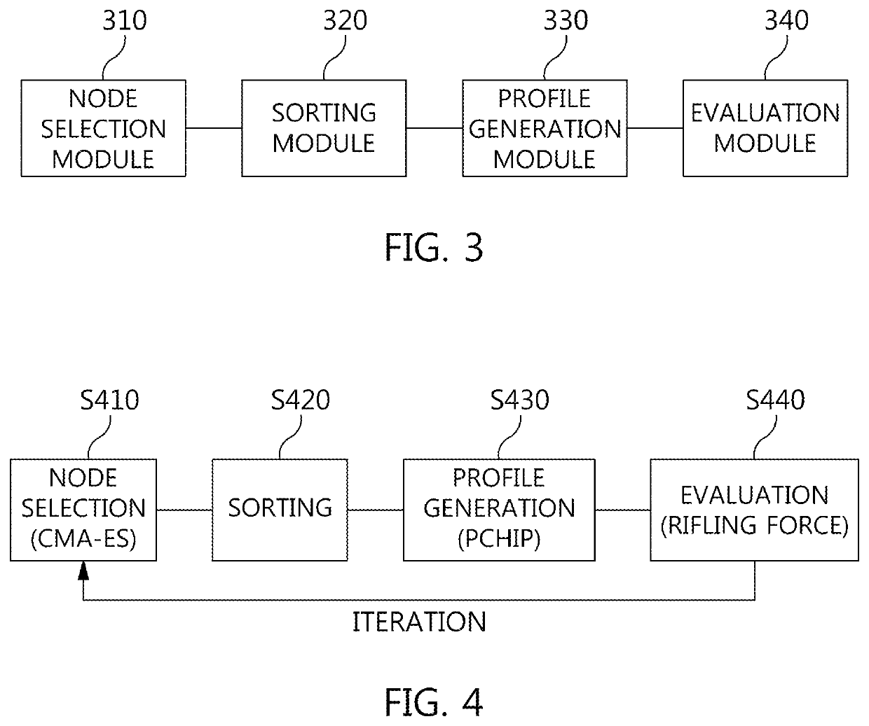
An apparatus for designing a rifling rate to increase a lifespan of a gun barrel includes: a node selection module selecting and distributing the predetermined number of node points according to preset constraints between preselected starting and end rifling angles; a sorting module sorting distributed node points; and a profile generation module calculating a rifling rate curve using sorted node points, and generating a rifling rate profile using the rifling rate curve.

Description

CROSS REFERENCE TO RELATED APPLICATION(S)[0001]This application claims the benefit of Korean Patent Application No. KR 10-2018-0137275, filed Nov. 9, 2018, which is hereby incorporated by reference in its entirety into this application.BACKGROUND OF THE INVENTION1. Technical Field[0002]The present invention relates to a gun barrel technology and, more particularly, to an apparatus and method for designing a rifling rate profile of an artillery to increase a lifespan of a gun barrel.2. Description of Related Art[0003]Because rifling force acting on a projectile when the projectile passes through a gun barrel is given as a function of a rifling angle α and a rifling angle change rate α′, it is possible to prevent the rifling force from being concentrated on a specific position of the gun barrel by designing the rifling rate to be appropriately changed from a breech to a muzzle.[0004]However, at the same time, in order for the projectile to fly steadily, a certain rifling rate should b...

Claims


Application Information

Patent Timeline
Patent Type & Authority Patents(United States)
IPC IPC(8): F41A21/18
CPCF41A21/18F41A21/16
Inventor AN, SEILOH, YUNJUNGCHA, KI-UP
Owner AGENCY FOR DEFENSE DEV
Learn More