Synthetic representation of a vascular structure

a vascular structure and synthetic representation technology, applied in the field of synthetic representation of vascular structures, can solve the problem that it is not easy for clinicians to match features within the angiographic image, and achieve the effect of improving the technique for interpreting angiograms

Active Publication Date: 2020-11-03
KONINKLJIJKE PHILIPS NV
View PDF13 Cites 2 Cited by
  • Summary
  • Abstract
  • Description
  • Claims
  • Application Information

AI Technical Summary

Benefits of technology

[0006]It would be advantageous to have an improved technique for interpreting angiograms.
[0013]To put this another way, the 3D model of the body part can be transformed, such as rotated, translated, or warped, such that a 2D projection of the 3D vascular structure of the 3D model looks similar to that to the angiogram. In this way, the synthetically generated 2D vascular structure looks to have been acquired by an (imaginary) X-ray acquisition unit whose X-ray source and detector were similarly positioned relative to the patient's body part as the real X-ray source and detector were positioned when the real angiogram was taken. Then, because the 3D vascular structure in the 3D model is known, i.e., all the component parts of the vascular tree are known and can be named, the 2D synthetic projection, which can have annotations applied to the vascular structure, can enable the structure within the 2D angiogram to be more easily interpreted.
[0016]In this manner, a generic 3D model of a body part can be utilised for all patients, and where the known vascular structure within the 3D model can be used to aid a clinician's interpretation of an actual angiogram. In this way, the clinician is better able to determine the direction through the heart the X-rays passed for a particular angiogram. In other words, the clinician is able to spatially orientate himself with respect to the heart when looking at the angiogram. Furthermore, because the 2D projection of the 3D modelled vascular structure is of a known structure, the clinician can easily determine the identity of parts of the vascular structure in the angiogram through reference to the 2D projection of the 3D modelled vascular structure. The clinician is able to easily identify the arteries in the angiogram by their anatomical names, through reference to the matching 2D projection of the 3D model that shows the 2D projection of the modelled vascular structure as if the 3D model of the heart had itself been subjected to X-ray analysis from the same direction as that used to acquire the angiogram. A clinician may be able to identify the branches and subsegments, however it can be cumbersome to synthesize the information gained from different angiograms into an artificial flattened diagram and utilization of the 3D model in the manner described aids this process.
[0017]The clinician is also provided with a means to help him in interpreting the 2D projection of the 3D model—the diagram. The benefit is at least twofold: he does not have to do the translation a) from image to an anatomical name and then b) from the anatomical name to the diagram. Furthermore, reprojected diagrams naturally allow to aggregate the information from different sequences (different views) into one unique model. Information can easily be gathered from different views into one structure that summarizes the findings in the final report.
[0035]In this manner, an easy way to annotate the coronary tree is provided.
[0042]By providing a medical system for providing a synthetic representation of a vascular structure a clinician is automatically provided with the required reporting information associated with the intervention. The clinician is provided with information regarding the names of the parts of the coronary tree of the patient, enabling full and accurate reporting of both an intervention that is to be conducted and reporting of an intervention that has been conducted. By providing a synthetic representation of a vascular structure, the clinician can easily in the future review the angiograms and understand their spatial context, and different clinicians can review the angiograms and be automatically provided with information relating to the vascular structure observed within the angiograms without having to interpret the images.

Problems solved by technology

However, the flattened schematic graph of the coronary arteries is far from the actual vascular structure as observed in an angiographic image, and as a result it is not straightforward for the clinician to match features within the angiographic image with those on the schematic graph of the coronary arteries.

Method used


Image

  • Synthetic representation of a vascular structure
  • Synthetic representation of a vascular structure
  • Synthetic representation of a vascular structure

Examples


Embodiment Construction

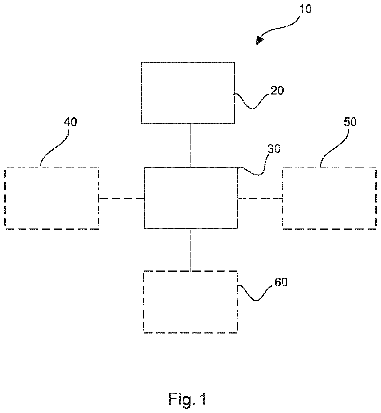
[0057]FIG. 1 shows an example of an apparatus 10 for providing a synthetic representation of a vascular structure. The apparatus comprises an input unit 20 and a processing unit 30. The input unit 20 is configured to provide at least one 2D X-ray image comprising 2D X-ray image data of a vascular structure of a patient's body part to the processing unit 30. The input unit 20 is also configured to provide a 3D model of the body part, the 3D model comprising a 3D modelled vascular structure to the processing unit 30. The processing unit 30 is configured to determine a 2D projection of the 3D model of the body part, the 2D projection of the 3D model of the body part comprising a 2D projection of the 3D modelled vascular structure. The processing unit 30 is also configured to transform the 3D model of the body part, wherein the transform of the 3D model of the body part comprises a determination of the pose of the 3D model of the body part such that a 2D projection of the 3D modelled va...


PUM


Abstract

The present invention relates to an apparatus for providing a synthetic representation of a vascular structure. It is described to provide (210) at least one 2D X-ray image comprising 2D X-ray image data of a vascular structure of a patient's body part is provided. A 3D model of the body part is provided (220), the 3D model comprising a 3D modelled vascular structure. A 2D projection of the 3D model of the body part is determined (230), the 2D projection of the 3D model of the body part comprising a 2D projection of the 3D modelled vascular structure. The 3D model of the body part is transformed (240). The transform of the 3D model of the body part comprises a determination of the pose of the 3D model of the body part such that a 2D projection of the 3D modelled vascular structure associated with the transformed 3D model of the body part is representative of the 2D X-ray image data of the vascular structure of the patient's body part. A medical report is generated (250) based on information determined from the 3D model.

Description

CROSS-REFERENCE TO PRIOR APPLICATIONS[0001]This application is the U.S. National Phase application under 35 U.S.C. § 371 of International Application No. PCT / EP2016 / 082870, filed on Dec. 29, 2016, which claims the benefit of European Patent Application No. 15307182.4, filed on Dec. 30, 2015. These applications are hereby incorporated by reference herein.FIELD OF THE INVENTION[0002]The present invention relates to an apparatus for providing a synthetic representation of a vascular structure to be typically integrated in an clinical interventional report, to a medical system for providing a synthetic representation of a vascular structure to be typically integrated in an clinical interventional report, and to a method for providing a synthetic representation of a vascular structure to be typically integrated in an clinical interventional report, as well as to a computer program element and a computer readable medium.BACKGROUND OF THE INVENTION[0003]In vascular treatments, for example ...

Claims


Application Information

Patent Timeline
Patent Type & Authority Patents(United States)
IPC IPC(8): G06T19/00G16H30/20A61B6/00G06T11/00G16H15/00G06T19/20G06T7/30A61B90/00
CPCG06T11/008G06T7/30A61B6/504G06T19/20G16H15/00G16H30/20G06T2207/30101G06T2219/2021A61B2090/367G06T2207/10116G06T2219/2016G06T2210/41G06T2207/30048G06T2219/004G06T2207/10124
Inventor AUVRAY, VINCENT MAURICE ANDRÉGAURIAU, ROMANE ISABELLE MARIE-BERNARDFLORENT, RAOULGROTH, ALEXANDRAWEESE, JUERGEN
Owner KONINKLJIJKE PHILIPS NV
Why Eureka
Try Eureka