

Satellite system having radio frequency assembly with signal coupling pin and associated methods
a radio frequency assembly and satellite technology, applied in the field of satellite systems, can solve the problems of difficult integration of amplifiers and other components, limited space for electronics and antennas, and even more difficult problems
- Summary
- Abstract
- Description
- Claims
- Application Information
AI Technical Summary
Benefits of technology
Problems solved by technology
Method used
Image

Examples
Embodiment Construction
[0023]The present description is made with reference to the accompanying drawings, in which exemplary embodiments are shown. However, many different embodiments may be used, and thus, the description should not be construed as limited to the particular embodiments set forth herein. Rather, these embodiments are provided so that this disclosure will be thorough and complete. Like numbers refer to like elements throughout, and prime notation is used to indicate similar elements in different embodiments.
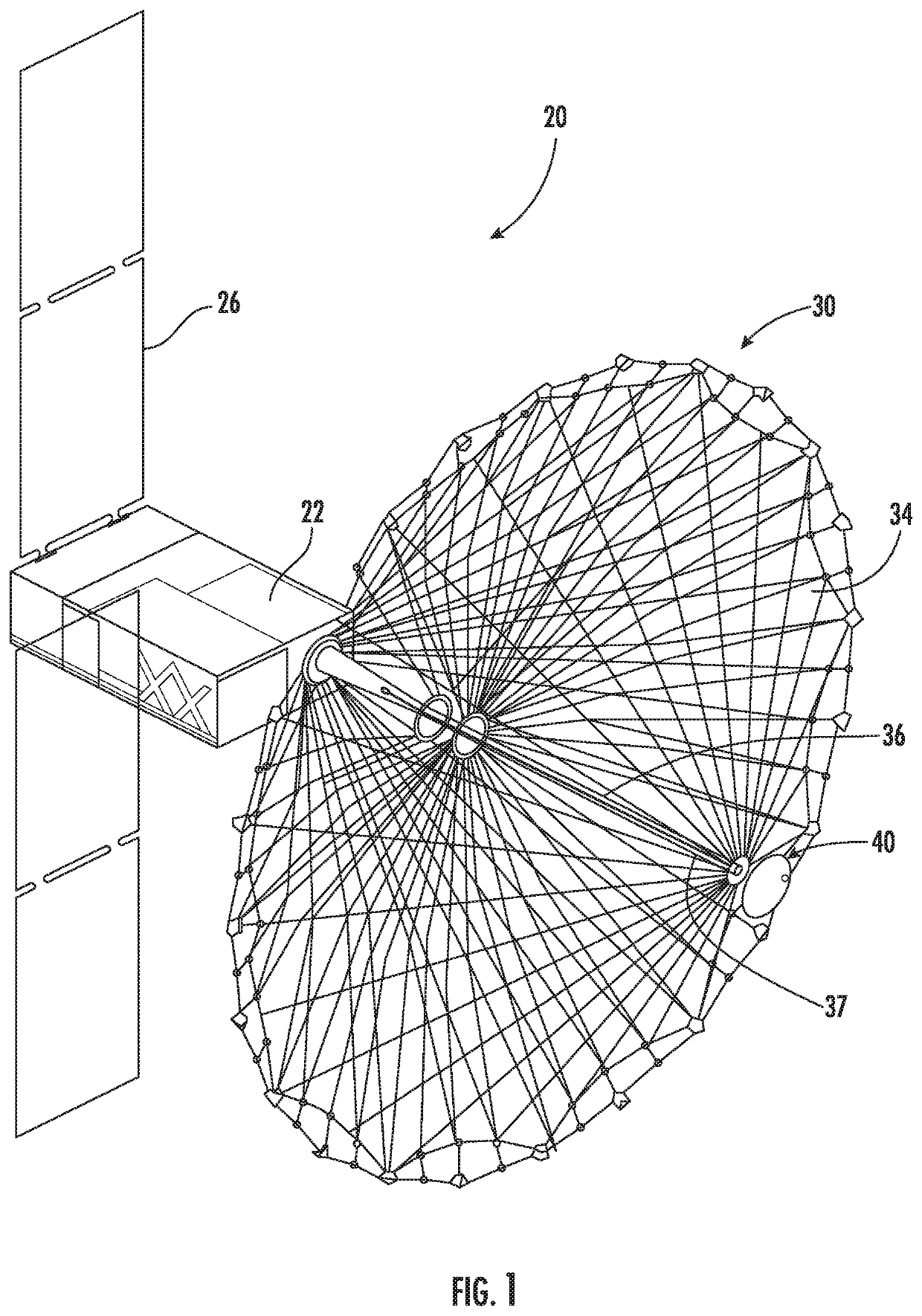
[0024]Referring initially to FIG. 1, a satellite system is illustrated generally at 20 that usually will orbit Earth in a Low Earth Orbit (LEO) as typical for small satellites, although any orbit altitude may be established depending on satellite functions. The satellite system 20 includes a satellite enclosure 22 that carries electronics such as a satellite transceiver and solar panels 26. The satellite system 20 in this example is a small form factor satellite. The satellite transceiv...
PUM
 Abstract
Description
Claims
Application Information