Method for operating a long stator linear motor with switch

a stator linear motor and switch technology, applied in the direction of electronic commutation motor control, transportation and packaging, propulsion systems, etc., can solve the problems of unfavorable collision of transport units, high demands on the movement of conveyors in the form of long stator linear motors, and high demands on conveyors

Active Publication Date: 2020-11-03
B&R IND AUTOMATION GMBH
View PDF15 Cites 1 Cited by
  • Summary
  • Abstract
  • Description
  • Claims
  • Application Information

AI Technical Summary

Benefits of technology

[0006]Embodiments of the subject invention provide a method with which a collision zone can be set in the region of a switch during operation of a conveyor in the form of a long stator linear motor, so that a collision of two transport units in the switch area can be safely avoided.
[0009]In order to simplify the determination of the lengths of the collision zone, a two-dimensional geometric shape can be selected as the two-dimensional object for the first transport unit, which surrounds the contour of the first transport unit and / or a two-dimensional geometric shape is selected as a two-dimensional object for the second transport unit which surrounds the contour of the second transport unit. With such defined, preferably simple, geometric shapes, such as rectangles, overlaps of the two transport units can be determined more easily and quickly.
[0011]With a fixed collision zone, travel through the switch can be easily controlled by allowing a second transport unit on the second conveyor section access to the collision zone in which the first transport unit is located, if a collision-free movement of the second transport unit into the collision zone is possible or a first transport unit on the first conveyor section is allowed access to the collision zone in which the second transport unit is located, if a collision-free movement of the first transport unit into the collision zone is possible. Thus, a transport unit outside the collision zone can be stopped until it is ensured that no collision can occur when entering the switch. For this purpose, the preceding transport unit must not necessarily have already left the switch, but both transport units can be moved simultaneously through the switch one after the other. In order to realize this, preferably, a minimum distance between the first transport unit and the second transport unit is set, which must be complied with, so that the first transport unit and the second transport unit can be moved through the switch without collision, wherein, to check for compliance with the minimum distance, the first transport unit on the first conveyor section in the collision zone is projected onto the second conveyor section in the collision zone, and / or vice versa. By projection, a simple check of a minimum distance is sufficient because the transport units appear on the same conveyor section. For collision monitoring, it no longer has to be distinguished whether the two transport units in the area of the switch are traveling on the same conveyor section or on different conveyor sections.

Problems solved by technology

A conveyor in the form of a long stator linear motor can be quite complex, even with several transport sections that can be interconnected by switches.
Such a conveyor thus places high demands on the control of the movement of the individual transport units.
The two-dimensional consideration of the transport units also takes into account a deflection of a transport unit on a curved section of the conveyor path in the region of the switch, which otherwise could lead to an undesired collision of the transport units.

Method used


Image

  • Method for operating a long stator linear motor with switch
  • Method for operating a long stator linear motor with switch
  • Method for operating a long stator linear motor with switch

Examples


Embodiment Construction

[0020]The particulars shown herein are by way of example and for purposes of illustrative discussion of the embodiments of the present invention only and are presented in the cause of providing what is believed to be the most useful and readily understood description of the principles and conceptual aspects of the present invention. In this regard, no attempt is made to show structural details of the present invention in more detail than is necessary for the fundamental understanding of the present invention, the description taken with the drawings making apparent to those skilled in the art how the several forms of the present invention may be embodied in practice.

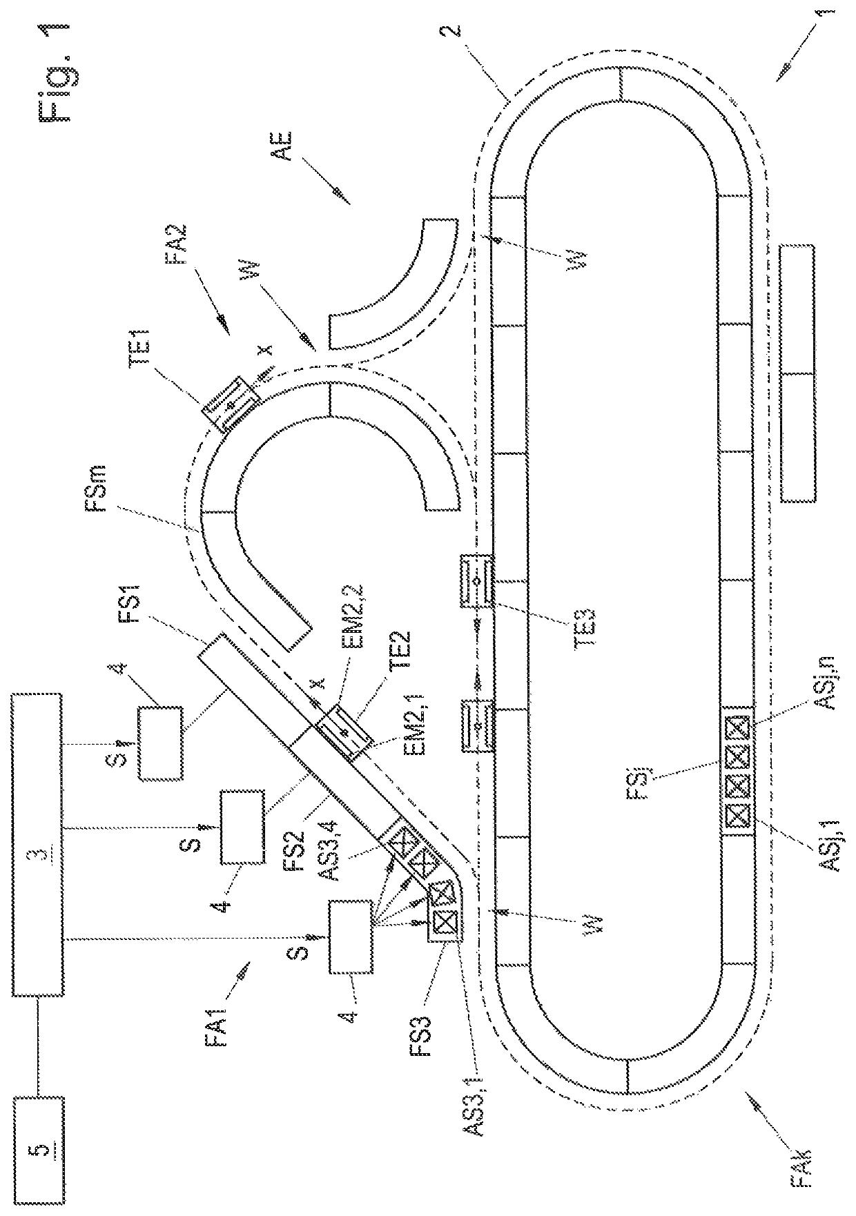
[0021]FIG. 1 shows an example of any structure of a conveyor 1 with a conveyor line 2 (indicated by the dashed line). The conveyor 1 is designed as a long stator linear motor and a plurality of transport units TEi, i∈N are provided, which can be moved along the conveyor line 2. The conveyor line 2 is essentially defined b...


PUM


Abstract

To safely avoid a collision of two transport units in the switch area during operation of a conveyor in the form of a long stator linear motor with a switch, a collision zone is provided in the switch area, wherein the collision zone extends from the beginning of the switch in each case a length on the respective conveyor section, and to define the collision zone, the transport units are considered as two-dimensional objects and a position of the first transport unit on the first conveyor section is determined, which the first transport unit is allowed to occupy, so that the second transport unit can be moved as a two-dimensional object along the second conveyor section without collision through the switch and a distance between this first position and the beginning of the switch is determined and at least this distance is used as the first length.

Description

CROSS-REFERENCE TO RELATED APPLICATIONS[0001]The present application claims priority under 35 U.S.C. § 119(a) of Europe Patent Application No. 18185539.6 filed Jul. 25, 2018, the disclosure of which is expressly incorporated by reference herein in its entirety.BACKGROUND1. Field of the Invention[0002]The invention relates to a method for operating a conveyor in the form of a long stator linear motor having a conveyor line with at least one switch, with which a first conveyor section of the conveyor line is connected to a second conveyor section of the conveyor line and the first conveyor section and the second conveyor section diverge in the region of the switch from the beginning of a switch, wherein a first transport unit and a second transport unit are moved along the conveyor line and to avoid collisions between the first transport unit and the second transport unit a collision zone is set in the region of the switch in which there is the risk of a collision between the first tr...

Claims


Application Information

Patent Timeline
Patent Type & Authority Patents(United States)
IPC IPC(8): H02K41/03B65G54/02H02P6/00H02P25/06
CPCB65G54/02H02K41/031H02P25/06H02P6/006B60L13/03B61B13/00H02K41/02B60L13/003B65G43/02B65G43/00B65G2812/99
Inventor HUBER, STEFANWALTER, DOMINICREICHENWALLNER, BENJAMIN
Owner B&R IND AUTOMATION GMBH
Why Eureka
Try Eureka