
Image Processing-Based Collision Avoidance System for Flight Vehicle and Flight Vehicle Including Same

a collision avoidance and flight vehicle technology, applied in the field of image processing-based collision avoidance systems for flight vehicles and flight vehicles including same, can solve the problems of high power system, high cost of radar system, and uav may encounter obstacles in the sky, so as to avoid vibration

Inactive Publication Date: 2020-09-03
KOREA ADVANCED INST OF SCI & TECH
View PDF3 Cites 2 Cited by
  • Summary
  • Abstract
  • Description
  • Claims
  • Application Information

AI Technical Summary

Benefits of technology

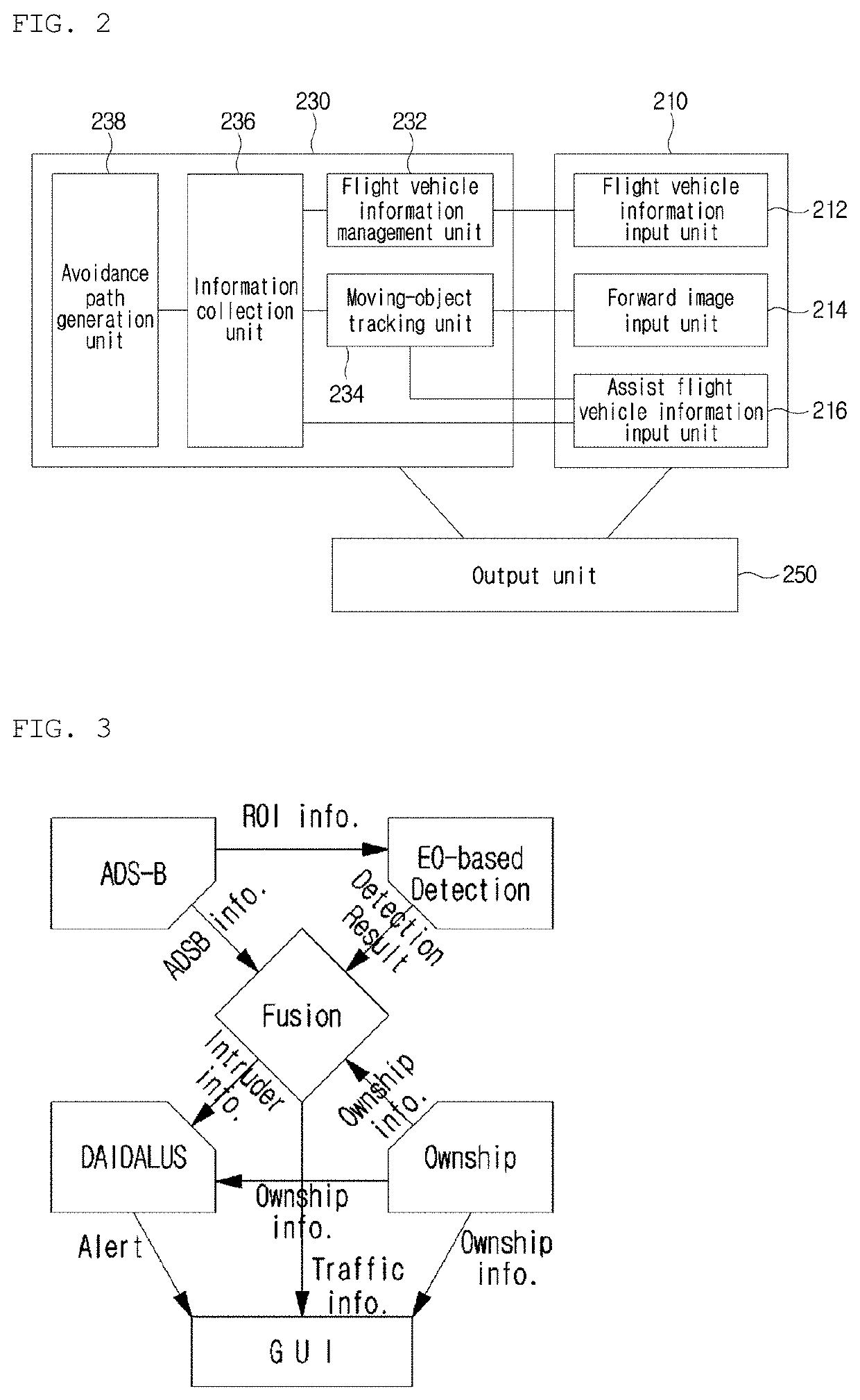
The present invention is a device and method for safely avoiding both cooperative and non-cooperative aircraft. It uses a moving-object tracking unit to enlarge the interest region and identify the type of object using deep learning. It is also able to handle deformation of the wing caused by the flight and can detect and track obstacles in the flight path stably.

Problems solved by technology

While the UAV is in operation, the UAV may encounter an obstacle in the sky.
Also, the existing technology, which includes the Global Positioning System (GPS), for preventing collision with aircrafts, and obstacles has a limit in that many obstacles are not recognized (or not quickly recognized) via the GPS device, the existing technology is dependent on altitude or terrain, and the GPS accuracy performance varies greatly with environment.
In the related art, in order to solve this problem, radar has been used, but the system using radar is costly and is a high power system.
Therefore, there is a limit in use in the private sector.
Herein, an image is received through a device equipped in the UAV, but it is impossible to stably receive an image of a forward area due to the movement of the UAV.
Thus, there is a problem with tracking the obstacle or determining whether the obstacle is an intruder.

Method used


Image

  • Image Processing-Based Collision Avoidance System for Flight Vehicle and Flight Vehicle Including Same
  • Image Processing-Based Collision Avoidance System for Flight Vehicle and Flight Vehicle Including Same
  • Image Processing-Based Collision Avoidance System for Flight Vehicle and Flight Vehicle Including Same

Examples


Embodiment Construction

[0050]Herein below, exemplary embodiments of the present invention will be described in detail with reference to the accompanying drawings such that the present invention can be easily embodied by those skilled in the art to which this present invention belongs. However, the present invention may be embodied in various different forms and should not be limited to the embodiments set forth herein.

[0051]In describing the embodiments of the present invention, if it is decided that the detailed description of known function or configuration related to the invention make the subject matter of the invention unclear, the detailed description is omitted. Also, parts that are not related to the description of the present invention are omitted from the drawings, and like reference numerals designate like parts.

[0052]In the present invention, when a constituent element is “coupled to”, “combined with”, or “connected to” another constituent element, it can be directly coupled to the other const...


PUM


Abstract

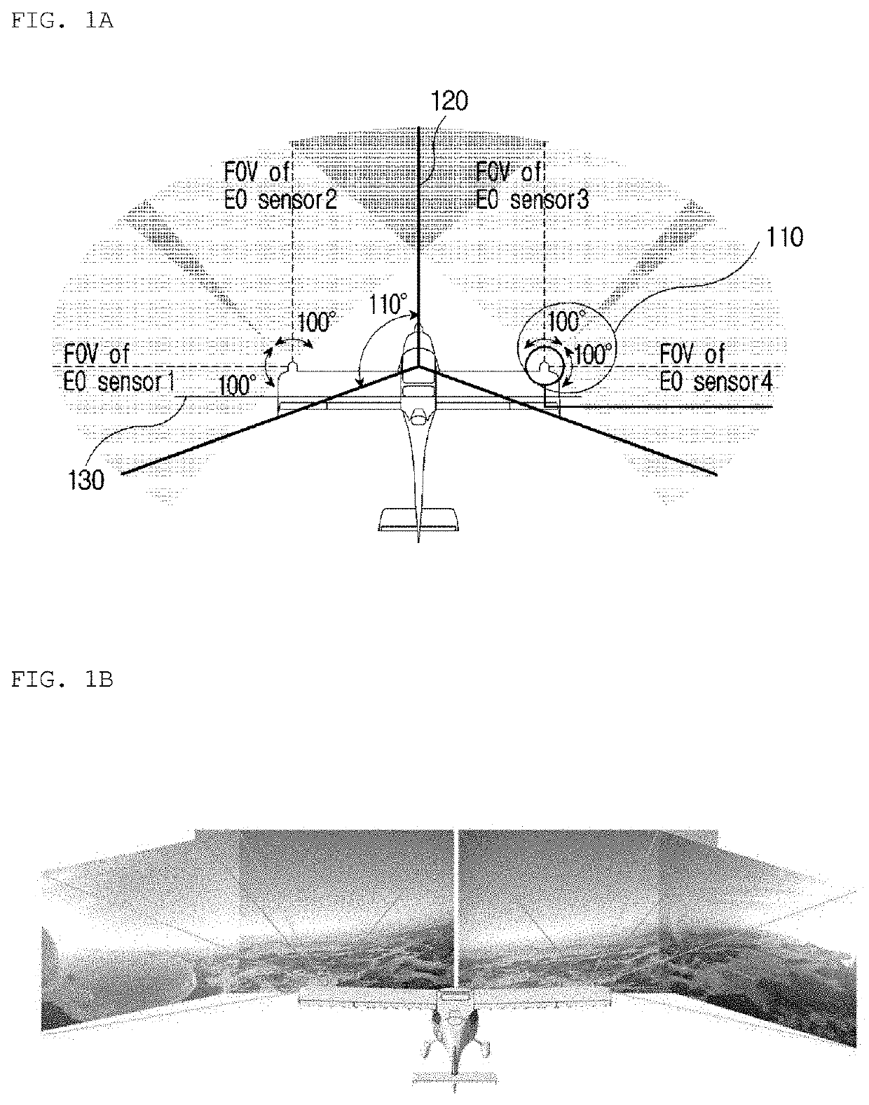
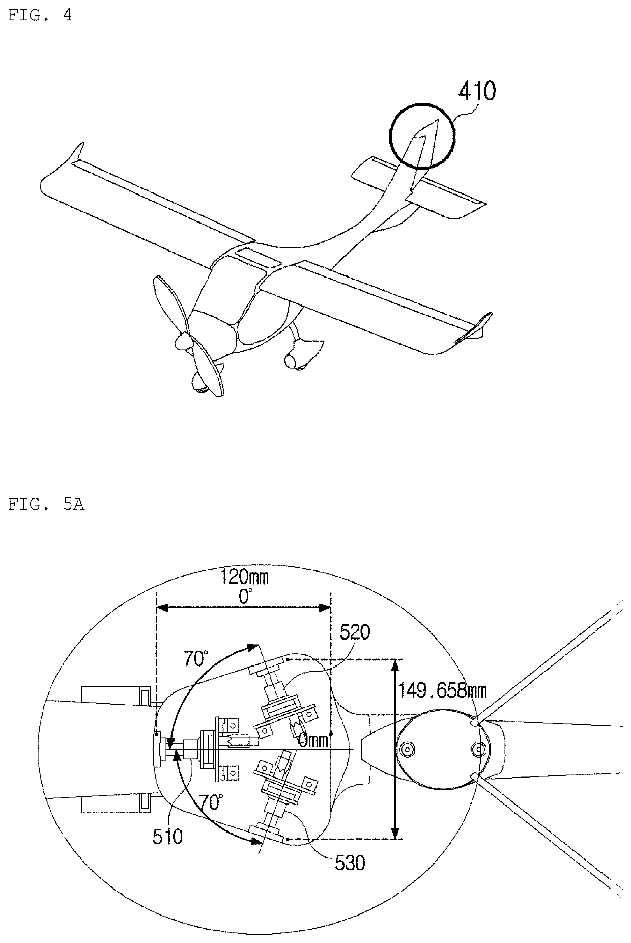
The present invention relates to an image processing-based collision avoidance method and system for a flight vehicle, and a flight vehicle including the system. The present invention proposes a method in which an interest region containing a moving object is detected from a received image; and the interest region is enlarged to identify a type of the moving object, wherein when the moving object is detected, the received image is filtered and the moving object is detected on the basis of movement in the filtered image. Further, in the present invention, a forward image input unit obtaining a forward image of a direction in which the flight vehicle moves is provided on a vertical tail wing that is positioned on a first axis of the flight vehicle, the moving object is detected from the forward image for tracking, and then an avoidance path is generated.

Description

CROSS REFERENCE TO RELATED APPLICATIONS[0001]The present application claims priority to Korean Patent Application No. 10-2019-0023834, filed Feb. 28, 2019 and Korean Patent Application No. 10-2019-0023835, filed Feb. 28, 2019, the entire contents of which are incorporated herein for all purposes by this reference.BACKGROUND OF THE INVENTIONField of the Invention[0002]The present invention relates to a method of detecting and avoiding an intruder on the basis of an image to prevent collision of a flight vehicle, and a device in which the method operates.Description of the Related Art[0003]In general, an unmanned aerial vehicle (UAV) refers to a flight vehicle that is operated by a pilot who controls the flight vehicle while not being on board. The unmanned aerial vehicle is firstly used for the case of conducting military actions which have a high probability of danger and loss of life, such as reconnaissance of enemy camps or attack on a target with missiles in combat situations, an...

Claims


Application Information

Patent Timeline
IPC IPC(8): G05D1/10G05D1/00G06T7/269G06T7/73G08G5/00G08G5/04G06N20/00
CPCG05D1/0094G06T2207/30252G05D1/1064G08G5/0069G06T7/269G08G5/045G06T7/74G06T2207/10016G06N20/00G08G5/0008G08G5/0021G08G5/0086G08G5/0078G06T7/254G06T2207/30261G06T2207/20036
Inventor SHIM, HYUN CHULLEE, JAE HYUNLEE, HAN SEOB
Owner KOREA ADVANCED INST OF SCI & TECH
Learn More