Method for producing a structural component

a manufacturing method and structural technology, applied in the direction of transportation and packaging, chemistry apparatus and processes, other domestic articles, etc., can solve the problems of high cost, time-consuming and cost-intensive manufacturing of multiple curved shell assemblies, and a very circuitous manufacturing process

Active Publication Date: 2020-11-10
AIRBUS OPERATIONS GMBH
View PDF23 Cites 0 Cited by
  • Summary
  • Abstract
  • Description
  • Claims
  • Application Information

AI Technical Summary

Benefits of technology

[0059]In accordance with a further embodiment of the method according to the invention for manufacturing a structural assembly, of the method according to the invention for manufacturing a semi-finished product and of the repair method according to the invention, the temperature is selected in a range of 250° C. to 375° C., preferably in a range of 275° C. to 375 ° C., more preferably in a range of 275° C. to 325° C. At temperatures in this range, tensions in the arrangement, the stack or the doubler can be relaxed when they are subjected to creep forming. With heating to temperatures in this temperature range, a plurality of advantageous effects can simultaneously be achieved: resilience or “spring-back” of the arrangement, the stack or the doubler after the deformation process can be prevented by relaxing the tension; in particular when AlMgSc alloys are used, the favourable properties of this material are fully or largely maintained in this temperature range; in addition, suitable thermoplastic plastics materials can be melted so as to connect the layers or assembly components or to connect the layer of the doubler to the structural assembly. The lack of resilience, the fact that the material properties are maintained, and the simultaneous melting thus make it possible for example to manufacture a fully deformed structural assembly of two or more individual components in a highly efficient manner in a single method step. Furthermore, in the corresponding embodiment of the second method according to the invention for manufacturing a structural assembly, the thermoplastic matrix of a composite component can soften in this temperature range in such a way that the composite component can likewise be deformed, making it possible to manufacture two precisely matching deformed assembly components in one operation.
[0060]In an embodiment of the method according to the invention for manufacturing a structural assembly, during the creep forming the arrangement is exposed to the temperature for a period of ten minutes or longer, preferably for a period in the range of ten minutes to approximately three hours, and more preferably for a period in the range of approximately 30 minutes to two hours.
[0061]In an embodiment of the method according to the invention for manufacturing a semi-finished product, during the heating the stack is exposed to the temperature for a period of ten minutes or longer, and preferably for a period in the range of ten minutes to approximately three hours.
[0062]In a development of the repair method according to the invention, the doubler is exposed to the temperature for a period of ten minutes or more, and preferably for a period in the range of ten minutes to approximately three hours.
[0063]In an embodiment of the first method according to the invention for manufacturing a structural assembly, it is ensured that after the creep forming and melting at least in part of the thermoplastic plastics material the arrangement can cool down again, the thermoplastic plastics material becoming solid again and durably connecting the first and second assembly component to form the structural assembly.
[0064]In a development of the second method according to the invention for manufacturing a structural assembly, it is ensured that after the creep forming the arrangement can cool down again, the thermoplastic plastics material transitioning back from the softened but not melted state into the solidified state. In this way, the geometry of the composite components which is achieved after the deformation is fixed.

Problems solved by technology

Nevertheless, manufacturing multiple curved shell assemblies is still time-consuming and cost-intensive.
Deforming skin members and reinforcing members for shell assemblies of this type, on the one hand, and fastening the reinforcing members to the skin members, on the other hand, in separate operations in each case, leads to a high expense for processing the workpieces and a very circuitous manufacturing process.
If the skin members and reinforcing members are deformed separately, great expense is required so as to ensure that these assemblies can subsequently be interconnected in a precise fit.

Method used


Image

  • Method for producing a structural component
  • Method for producing a structural component
  • Method for producing a structural component

Examples


first embodiment

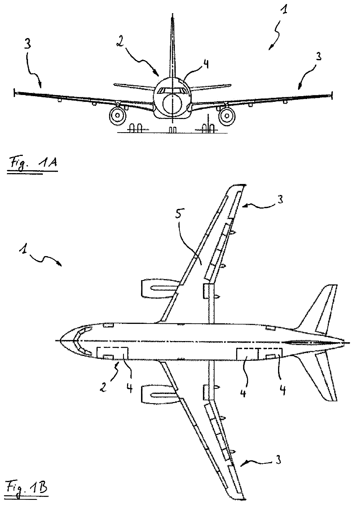
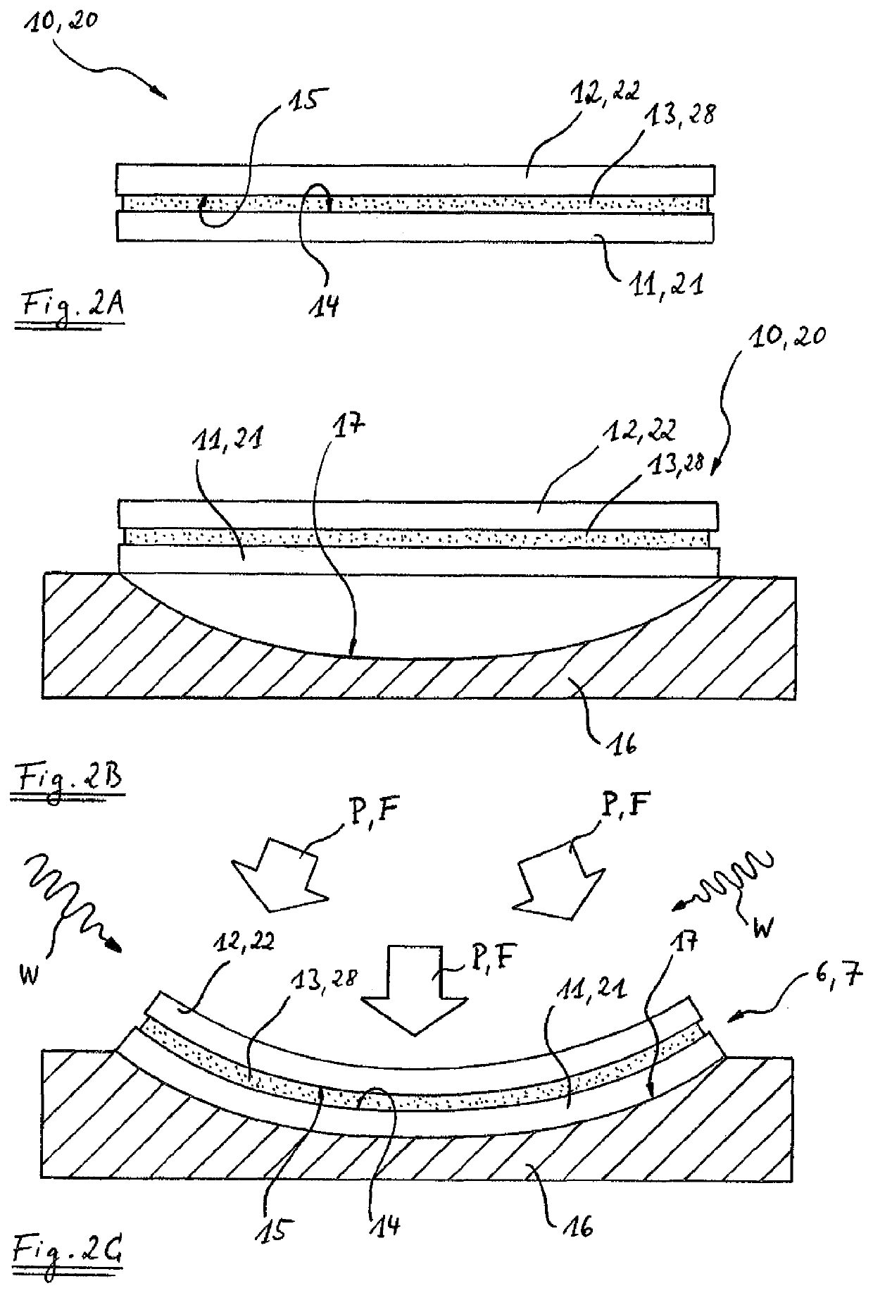
[0111]FIGS. 2A to 2C show the manufacture of a structural assembly 6 and a semi-finished product 7 in accordance with the invention. The structural assembly 6 may be a wing shell 5 or a fuselage shell 4 of the aircraft 1, but may also be any other structural assembly from the field of air or space travel or else from other technical fields, for example motor vehicle or construction technology.

[0112]FIG. 2A shows an arrangement 10 which is formed by arranging a second assembly component 12 on a first assembly component 11. A sheet 28 of a thermoplastic plastics material 13 is provided between the two assembly components 11 and 12. In FIG. 2A, the sheet 28 of the thermoplastic plastics material 13 is not yet connected to the two assembly components 11 and 12, but can, as shown in FIG. 4, be laid between the first assembly component 11 and the second assembly component 12 in the form of a film or foil so as to form the arrangement 10. Alternatively, the thermoplastic plastics material ...

second embodiment

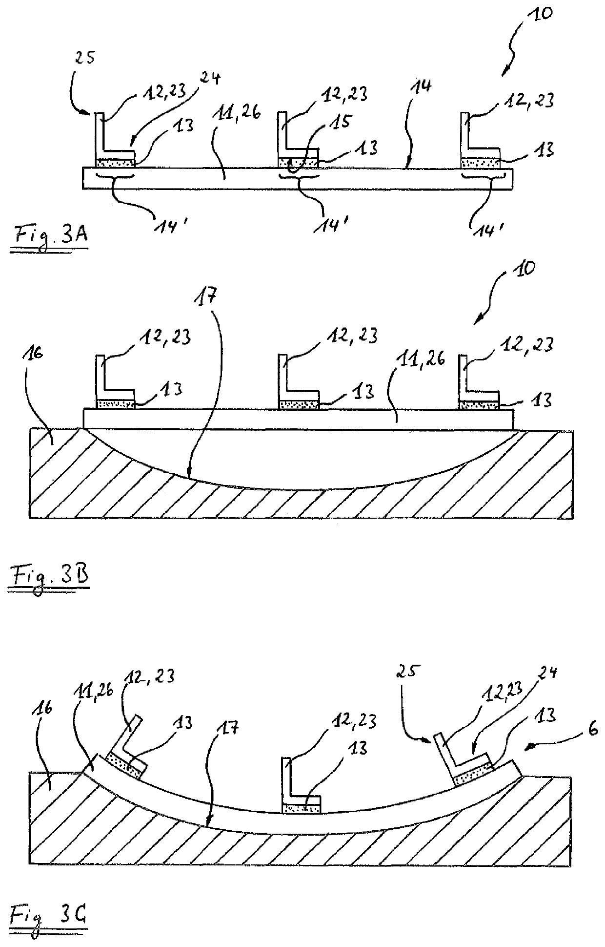
[0121]FIG. 6 shows two options for preparing the thermoplastic plastics material 13 for manufacturing the structural assembly 6 in accordance with the second embodiment, either as a film or foil, which is laid between the first limb 24 and the shell skin 26, or as a coating of a lower surface 15 of the first limb 24 of the stringer 23, for example by thermally spraying the thermoplastic plastics material 13 onto the lower surface 15 of the stringer foot. As is sketched in FIG. 6A, in addition or as an alternative to the lower surface 15 of the first limb 24 of the stringer 23, a surface portion 14′ of the upper surface 14 of the shell skin 26 may also be coated with the thermoplastic plastics material 13. So as to ensure good adhesion of the thermoplastic plastics material 13 to the first and second assembly components 11 and 12 in this case too, in FIGS. 6 and 6A to the shell skin 26 and the stringer 23, the upper surface 14 or at least the surface portions 14′ of the upper surface...

fifth embodiment

[0126]In accordance with the invention, as illustrated in

[0127]FIGS. 9A to 9C, before forming an arrangement 10, initially one or more third assembly components 31 may be connected to a first assembly component 11, other than by means of a thermoplastic plastics material. The first assembly component 11 of FIG. 9A is in the form of a substantially planar sheet of an AlMgSc alloy, the thickness of the sheet being for example between 0.8 mm and 6.0 mm , preferably 0.8 mm to 3.8 mm, more preferably 0.8 mm to 2.0 mm. In the finished structural assembly 6, the first assembly component 11 forms a shell skin 26. FIG. 9A only shows a third assembly component 31, which in this example is in the form of a stringer, the longitudinal direction of which extends substantially parallel to the plane of the drawing. The stringer serves to reinforce the shell skin 26 in the structural assembly 6, and is already welded to the first assembly component 11 in FIG. 9A. The welding may for example take pla...


PUM

PropertyMeasurementUnit
temperatureaaaaaaaaaa
thicknessaaaaaaaaaa
temperaturesaaaaaaaaaa

Abstract

A method for manufacturing a structural assembly comprising at least two assembly components interconnected by means of a thermoplastic plastics material, and useful in the field of aviation or space travel. First, a first assembly component and a second assembly component are provided and arranged so as to form an arrangement. Second, the arrangement is subjected to creep forming at a temperature which is selected in such a way that the thermoplastic plastics material melts at least in part during the creep forming so as to connect the first assembly component and the second assembly component. The invention further relates to structural assemblies, in particular for an aircraft or spacecraft, and to an aircraft or spacecraft comprising a structural assembly of this type.

Description

CROSS-REFERENCES TO RELATED APPLICATIONS[0001]This application claims the benefit of the U.S. Provisional Application No. 61 / 466,964, filed on Mar. 24, 2011, and of the German patent application No. 10 2011 006 032.4 filed on Mar. 24, 2011, and of the international Patent Application No. PCT / EP2012 / 055223, filed Mar. 23, 3013, the entire disclosures of which are incorporated herein by way of reference.FIELD OF THE INVENTION[0002]The present invention relates to a method for manufacturing a structural assembly, in particular for aviation or space travel, to a method for manufacturing a semi-finished product and to a repair method for a structural assembly. The invention further relates to a semi-finished product for manufacturing a structural assembly, to a semi-finished product for repairing a structural assembly, to structural assemblies, in particular for an aircraft or spacecraft, and to an aircraft or spacecraft comprising a structural assembly of this type.[0003]Although the pr...

Claims


Application Information

Patent Timeline
Patent Type & Authority Patents(United States)
IPC IPC(8): B32B37/04B29C65/48B21D21/00B32B15/08B32B15/20B32B7/12B29C73/10B29C70/84B32B38/18B21D22/02B29D99/00B64C1/12B29C70/08B32B38/16B29C65/50B29C51/00B29C65/00B29K101/12
CPCB32B7/12B29D99/001B64C1/12B29C65/481B32B38/1866B32B15/08B29C73/10B21D22/022B32B37/04B29C70/84B32B15/20B21D21/00Y10T156/1002B32B2398/20B29C66/026B29C65/5057B32B2311/00B32B2605/18B32B38/162Y02T50/40B32B2262/02Y10T428/31678Y10T428/24628B32B2262/106B29K2101/12B29C51/002B32B2262/101B29C70/088B29C65/4815B29C66/112B29C66/131B29C66/474B29C66/721B29C66/1122B29C66/45B29C66/7212B29C66/524B29C66/72321B29K2307/04B29K2309/08
Inventor PACCHIONE, MARCOFIDEU, PAULIN
Owner AIRBUS OPERATIONS GMBH
Why Eureka
Try Eureka