Electric shaver

a technology of electric shaver and shaver blade, which is applied in the direction of metal working apparatus, etc., can solve the problems of affecting the comfort of shaver handling, affecting the balance of the entire shaver, and affecting the smooth operation of the shaver

Active Publication Date: 2020-11-17
BRAUN GMBH
View PDF62 Cites 0 Cited by
  • Summary
  • Abstract
  • Description
  • Claims
  • Application Information

AI Technical Summary

Benefits of technology

[0013]It is an objective underlying the present invention to provide for an improved electric shaver avoiding at least one of the disadvantages of the prior art and / or further developing the existing solutions. A more particular objective underlying the invention is to allow the shaver head self-adjusting of its position relative to the handle without restrictions to the drive train and without restrictions to the support structure's kinematics due to collisions with the drive unit.
[0014]A further objective underlying the invention is to allow for an easy, well-balanced handling of the shaver with better self-adaption of the angular position of the shaver head to the skin contour to be shaved, including a better responsiveness of self-adjusting swivel and tilt movements of the shaver head to changing skin contours when moving the shaver head along the skin contour to be shaved.
[0015]A still further objective underlying the invention is to achieve a highly efficient driving of the shaver's cutter elements as well as self-adjustment of the shaver head to the skin contour to be shaved with less pressure applied to the functional shaver head surface contacting the skin contour and / or a quicker readjustment of the shaver head into its neutral position with less restoring forces.
[0017]More particularly, said pair of link arms may be arranged in a standing configuration with the head joints of the link arms connecting to the shaver head part being further away from the handle than the handle joints of the link arms connecting to the handle or base part. In combination with the motor being arranged inside the handle below the handle joints of the link arms so that the four point linkage is arranged between the shaver head and the motor and the shaft extending from the handle into the shaver head, an improved kinematics for the shaver head can be achieved with less restrictions to the arrangement and positioning of the link arms as well as a balanced handling of the shaver can be achieved. As the shaft, with its rotatory axis, extending substantially parallel to the handle's longitudinal axis or slightly inclined thereto, is a rather slim element not needing much space transverse to its rotatory axis, there is much space for the four-joint linkage, in particular in a central region of the shaver body, thereby allowing for desired kinematics of the shaver head's movable support structure. Nevertheless, the shaver is well balanced due to the motor's weight being in the handle. In addition, driving efficiency can be improved due to the shaft being a rather stiff transmitter subject to less bending than a rocker bar even when designed with small dimensions to save weight.
[0018]Contrary to a hanging or pendulum arrangement of the link arms where—when considering the shaver in an upright position with the shaver head above the handle—the upper ends of the link arms are connected to the handle and the hanging lower ends of the link arms are connected to the shaver head, such standing configuration provides for additional space that can be used for the drive train, and for a better kinematics of the shaver head support. As in such standing configuration—when considering the aforementioned upright position of the shaver—the lower end portions of the link arms are connected to the handle or base part and the upper end portions of the link arms are connected to the shaver head part, the handle or base part does not need to extend deeply into the shaver head to reach the upper ends of the link arms saving considerable space in the region of the shaver head, thus giving more freedom and space to the drive train extending through the shaver head.

Problems solved by technology

Due to such motor arrangement inside the shaver head, the entire shaver is no longer balanced, but top heavy in terms of weight distribution.
Furthermore, due to the space required for the motor in the shaver head, it is rather difficult to position a second pivoting axis, i.e. a tilting axis and a swivel axis allowing for multi-axial movements of the shaver head relative to the handle.
Due to such arrangement of the drive unit, the entire shaver is no longer balanced, but top-heavy, thus impairing a comfortable handling of the shaver.
Additionally, the shaver head becomes rather bulky when the motor is in the head what makes it sometimes difficult to shave smaller skin portions such as the face portion between the nose and the lips, and furthermore, the kinematics of the four joint linkage is restricted when the motor is arranged at the top of the handle between the link arms.
Furthermore, driving efficiency is restricted due to bending of the rocker arms.

Method used


Image

  • Electric shaver
  • Electric shaver
  • Electric shaver

Examples


Embodiment Construction

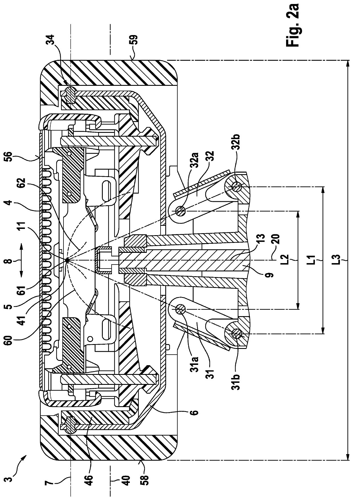
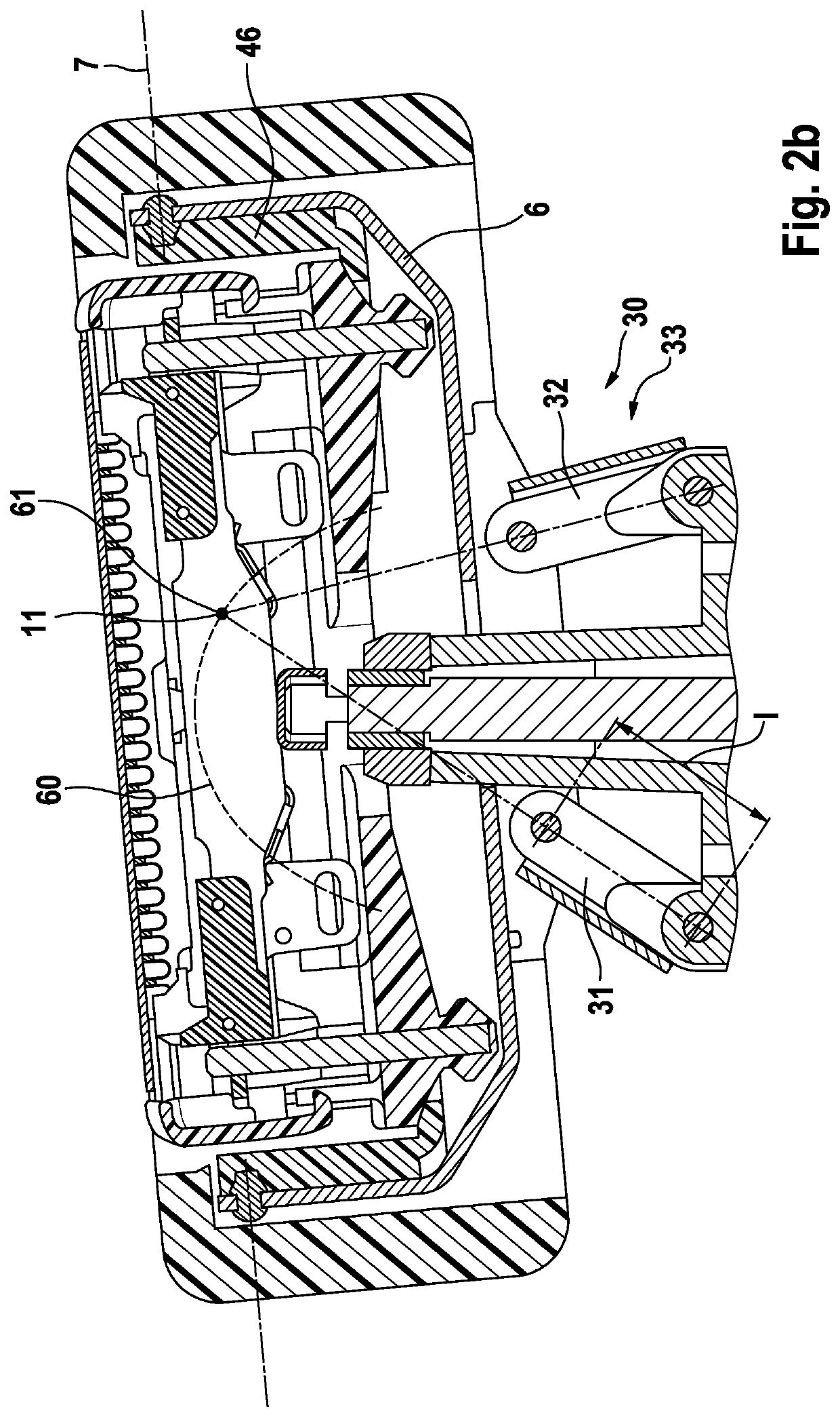
[0032]In order to achieve a responsive self-adjustment of the angular position of the cutter element to the skin and to avoid collisions between the drive train for driving the cutter element and the support structure, the four-joint linkage may include a pair of link arms arranged in an upright, standing configuration where the head joints of the link arms connected to the shaver head part are further away from the handle than the handle joints of the link arms connected to the handle or a base part connected to such handle. Such standing link arm configuration does not only give the drive train more space to extend in the region of the support structure, but also improves the shaver head kinematics to allow angular adjustment of the shaver head under less contact pressure from the skin to be shaved as the standing link arms are more willing to leave its position than hanging pendulum arms. In addition, such standing link arm configuration allows for an improved arrangement of the ...


PUM


Abstract

Electric shaver provided with a handle and a shaver head including at least one drivable cutter element, wherein said shaver head is connected to said handle by means of a support structure providing for a swivel and / or tilting axis about which said shaver head may swivel or tilt relative to said handle, wherein said support structure includes a pair of link arms forming a four-joint linkage with each link arm having a head joint connected to a shaver head part and a handle joint connected to the handle or a base part connected thereto.

Description

FIELD OF THE INVENTION[0001]The present invention relates to an electric shaver having a shaver head that may self-adapt its angular position to the skin contour. More particularly, the present invention relates to an electric shaver comprising a handle and a shaver head including at least one drivable cutter element, wherein said shaver head is connected to said handle by means of a support structure providing for a swivel and / or tilting axis about which said shaver head may swivel or tilt relative to said handle, wherein said support structure includes a pair of link arms forming a four-joint linkage with each link arm having a head joint connected to a shaver head part and a handle joint connected to the handle or a base part connected thereto.BACKGROUND OF THE INVENTION[0002]Electric shavers usually have one or more cutter elements driven by an electric drive unit in an oscillating manner where the cutter elements reciprocate under a shear foil, wherein such cutter elements or u...

Claims


Application Information

Patent Timeline
Patent Type & Authority Patents(United States)
IPC IPC(8): B26B19/04B26B19/06B26B19/38B26B19/28
CPCB26B19/384B26B19/386B26B19/046B26B19/063B26B19/284B26B19/042B26B19/28B26B19/048
Inventor KRAUSS, JOACHIMFISCHER, UWEROEDER, ROMANERNDT, ANDREASGLEICH, DETLEFLUDAESCHER, UWE
Owner BRAUN GMBH
Why Eureka
Try Eureka