
Blade adapter for wind turbines

a technology for wind turbines and adapters, which is applied in the direction of wind turbines, wind motor control, wind turbines, etc., can solve the problems of limited production engineering requirements, limited rotor blade length, and limited rotor blade maximum length, so as to increase the rotor diameter

Active Publication Date: 2020-11-24
SIEMENS GAMESA RENEWABLE ENERGY SERVICE GMBH
View PDF30 Cites 3 Cited by
  • Summary
  • Abstract
  • Description
  • Claims
  • Application Information

AI Technical Summary

Benefits of technology

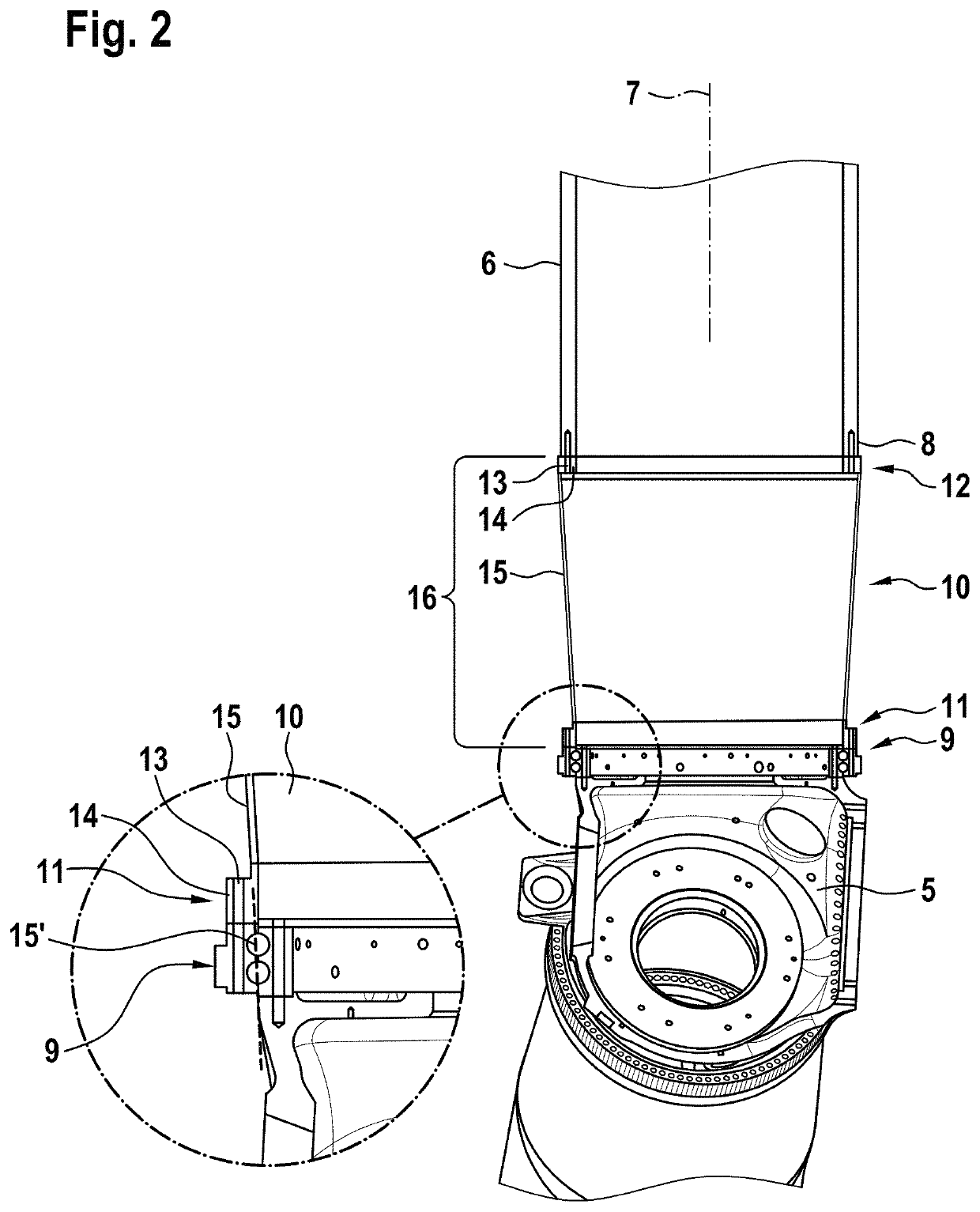
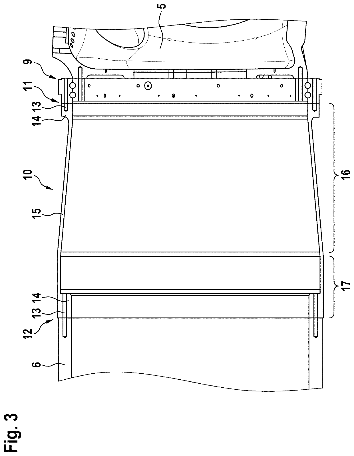
[0012]According to aspects of the invention, the wall of the blade adapter, which is basically of hollow design, widens in the form of a truncated cone, in at least one portion, in the direction of the end provided for connection of the rotor blade. It has been found that such a shape is advantageous for the transmission of weight and wind forces from the rotor blades to the rotor hub, in particular in respect of a uniform distribution of the load over the circumference of the blade adapter, and therefore in respect of a uniform transmission of force into the rotor blade bearing. It is preferred if the portion of the wall of the blade adapter that is closest to the first end is designed in the form of a truncated cone.
[0027]The rotor blades of the wind turbine in this case are each mounted on the rotor hub so as to be rotatable about a rotor axis. Owing to the stiffness that can be achieved in the region of the connection with a blade adapter according to the invention, which is normally significantly above the stiffness of a rotor blade in the region of its blade root, the forces acting upon the rotor blade bearings can be distributed more uniformly over the circumference, such that load peaks in the rotor blade bearing can be reduced.

Problems solved by technology

The length of the rotor blades, however, besides being limited by production engineering requirements, is limited in particular by the necessary transportability of the rotor blades.
Both for transport over land, for on-shore wind turbines, and over water, for off-shore wind turbines, there are limitations, arising from logistics, for the maximum length of rotor blades.
However, closer examination of the blade extenders known from the prior art has shown that, when such extenders are used, the forces acting on the rotor hub, and in particular on the bearings provided for the rotation of the rotor blades about their respective rotor axis, are increased and frequently are unevenly distributed over the circumference of the rotor blade bearing.
Consequently, there is the risk of increased wear or damage to the rotor blade bearing.
In order to prevent this, the rotor blade bearing can in principle be reinforced, as compared with use without blade extenders, but this is generally associated with increased costs and increased weight.

Method used


Image

  • Blade adapter for wind turbines
  • Blade adapter for wind turbines
  • Blade adapter for wind turbines

Examples


Embodiment Construction

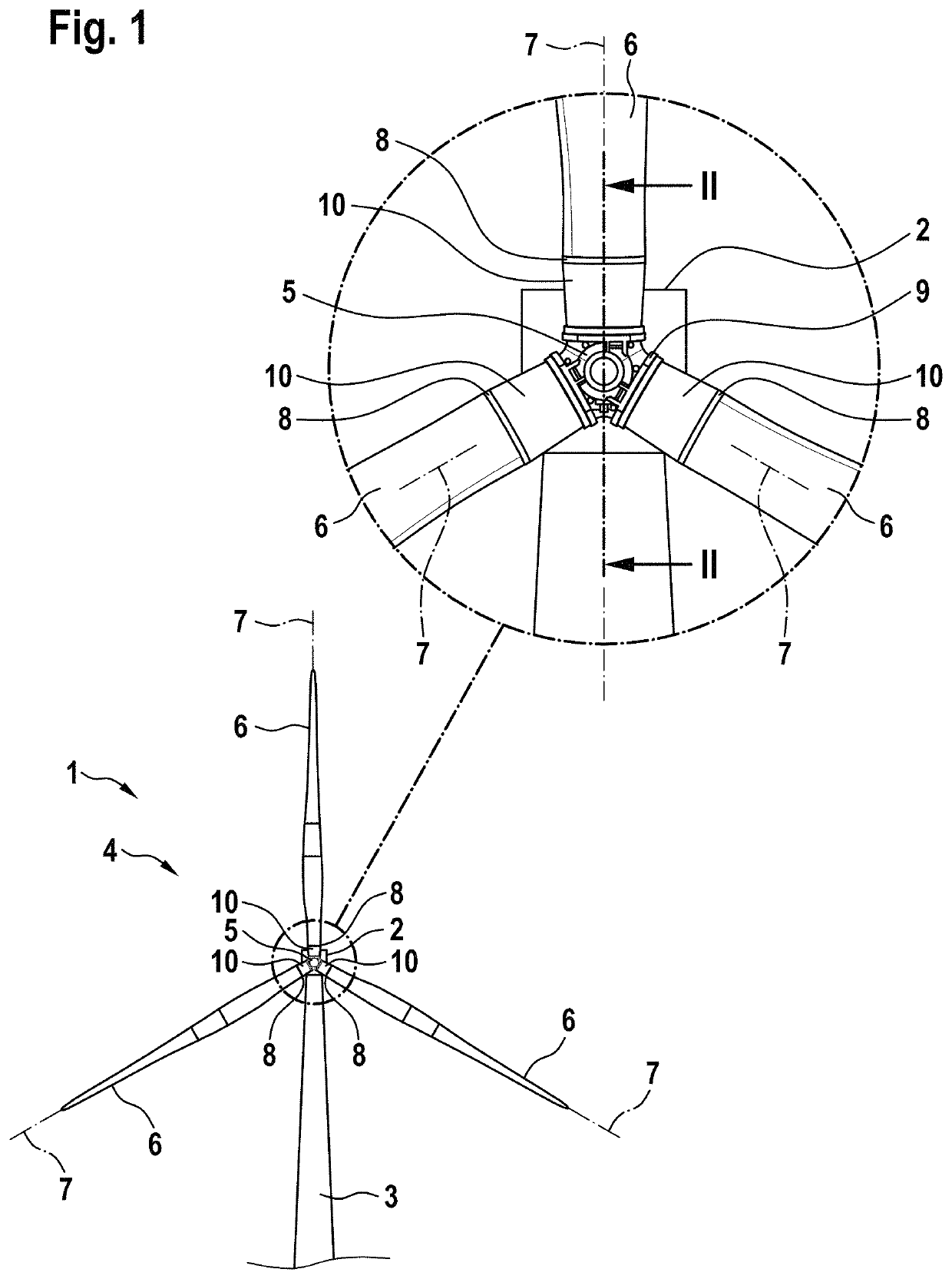
[0036]A wind turbine 1 according to the invention is represented schematically in FIG. 1. The wind turbine 1 comprises a rotor 4, which is arranged on a nacelle 2 so as to be rotatable about a rotor axis, perpendicularly in relation to the blade axis, and which can drive a generator (not represented) present in the nacelle 2. For the purpose of altering the azimuthal orientation of the rotor 4, the nacelle 2 is arranged on the tower 3 so as to be rotatable about a perpendicular axis.

[0037]The rotor 4 comprises three rotor blades 6, attached to a rotor hub 5, which are each rotatable about a rotor blade axis 7 for the purpose of setting the blade pitch angle. Blade adapters 10 according to the invention are provided between the respective blade roots 8 of the rotor blades 6 and the rotor hub 5.

[0038]The blade adapters 10 are now explained in greater detail on the basis of FIG. 2, in which the blade adapter 10 of the rotor blade 7, pointing upward in FIG. 1, is shown by way of example...


PUM


Abstract

A blade adapter for rotor blades of wind turbines, for increasing the rotor diameter, has a first end for attaching to the rotor hub, and a second end, spaced apart in the axial direction, for connecting to the blade root of a rotor blade. In addition, the blade adapter, at its first and second end, has a pitch circle for connecting to the rotor hub or to the rotor blade, wherein the wall of the blade adapter extending in the axial direction is open outwardly, in the form of a truncated cone, from the first end toward the second end, in at least one portion.

Description

CROSS-REFERENCE TO RELATED APPLICATIONS[0001]This application claims the priority of German Application No. 10 2017 004 056.7, filed Apr. 27, 2017, the entire contents of which are incorporated herein by reference.FIELD OF THE INVENTION[0002]The invention relates to a blade adapter for rotor blades of wind turbines, for the purpose of increasing the rotor diameter, and to a wind turbine having such blade adapters.BACKGROUND OF THE INVENTION[0003]Wind turbines are known from the prior art. They normally comprise a rotor, which is arranged on a nacelle so as to be rotatable about a substantially horizontal axis, the nacelle being arranged on a tower so as to be rotatable about a vertical axis. The rotor drives a generator optionally via a rotor shaft and a transmission. A wind-induced rotational motion of the rotor can thus be converted into electrical energy, which can then, via inverters and / or transformers—also at least partly directly, depending on the design of the generator—be f...

Claims


Application Information

Patent Timeline
Patent Type & Authority Patents(United States)
IPC IPC(8): F03D80/10F03D1/06F03D7/02F03D80/70
CPCF03D80/70F03D1/0675F03D7/0224F03D1/0658F05B2240/2211F05B2250/232F05B2240/313F05B2240/202Y02E10/72F05B2240/50F03D1/065
Inventor TREDE, ALF
Owner SIEMENS GAMESA RENEWABLE ENERGY SERVICE GMBH
Learn More