Display apparatus and method of controlling display apparatus

a display apparatus and display device technology, applied in the direction of instruments, computing, electric digital data processing, etc., can solve the problems of inability to generate timing signals in short time units, unstable operation of counter circuits, increased consumption of timing generation devices, etc., to achieve stable output, improve display definition, and reduce consumption power

Active Publication Date: 2020-11-24
SAKAI DISPLAY PROD
View PDF3 Cites 0 Cited by
  • Summary
  • Abstract
  • Description
  • Claims
  • Application Information

AI Technical Summary

Benefits of technology

[0010]According to a display apparatus and a method for controlling a display apparatus in an Embodiment of the present disclosure, a scanning clock signal adjusted in a short time unit can be stably obtained even when a low-frequency clock signal is used as a master clock signal, making it possible to reduce consumed power and inexpensively provide a display apparatus with an improved display definition.

Problems solved by technology

In such a timing generation device, there is a problem that, in a case the frequency of a clock signal input to the counter circuit is high, the number of bits required for the counter circuit increases, so that consumed power of the timing generation device increases and the operation of the counter circuit becomes unstable.
However, if the frequency of the operating clock signal is low, a timing signal adjusted in a short time unit cannot be generated.
Therefore, for a display apparatus for which a highly-accurate timing signal is required with upsizing of the display area and high resolution of video, it is difficult to apply a timing generation device only operating with a low-frequency operating clock signal.
On the other hand, if one seeks to stably operate a counter circuit with a high-frequency operating clock signal in order to generate a timing signal adjusted in a short time unit, an inexpensive logic IC (integrated circuit) such as a CPLD (complex programmable logic device) cannot be applied, so that, for example, an expensive logic IC such as an FPGA (field programmable gate array) needs to be used.
Therefore, the cost of manufacturing the display apparatus increases.
However, due to the above-described reasons, it is difficult to generate a highly-accurate scanning clock signal stably and inexpensively with low consumed power.

Method used


Image

  • Display apparatus and method of controlling display apparatus
  • Display apparatus and method of controlling display apparatus
  • Display apparatus and method of controlling display apparatus

Examples


embodiment 1

[0022]Below, Embodiment 1 is described with reference to the drawings. In each of the drawings, the same letter is affixed to portions having the same function.

Configuration of Display Apparatus According to Embodiment 1

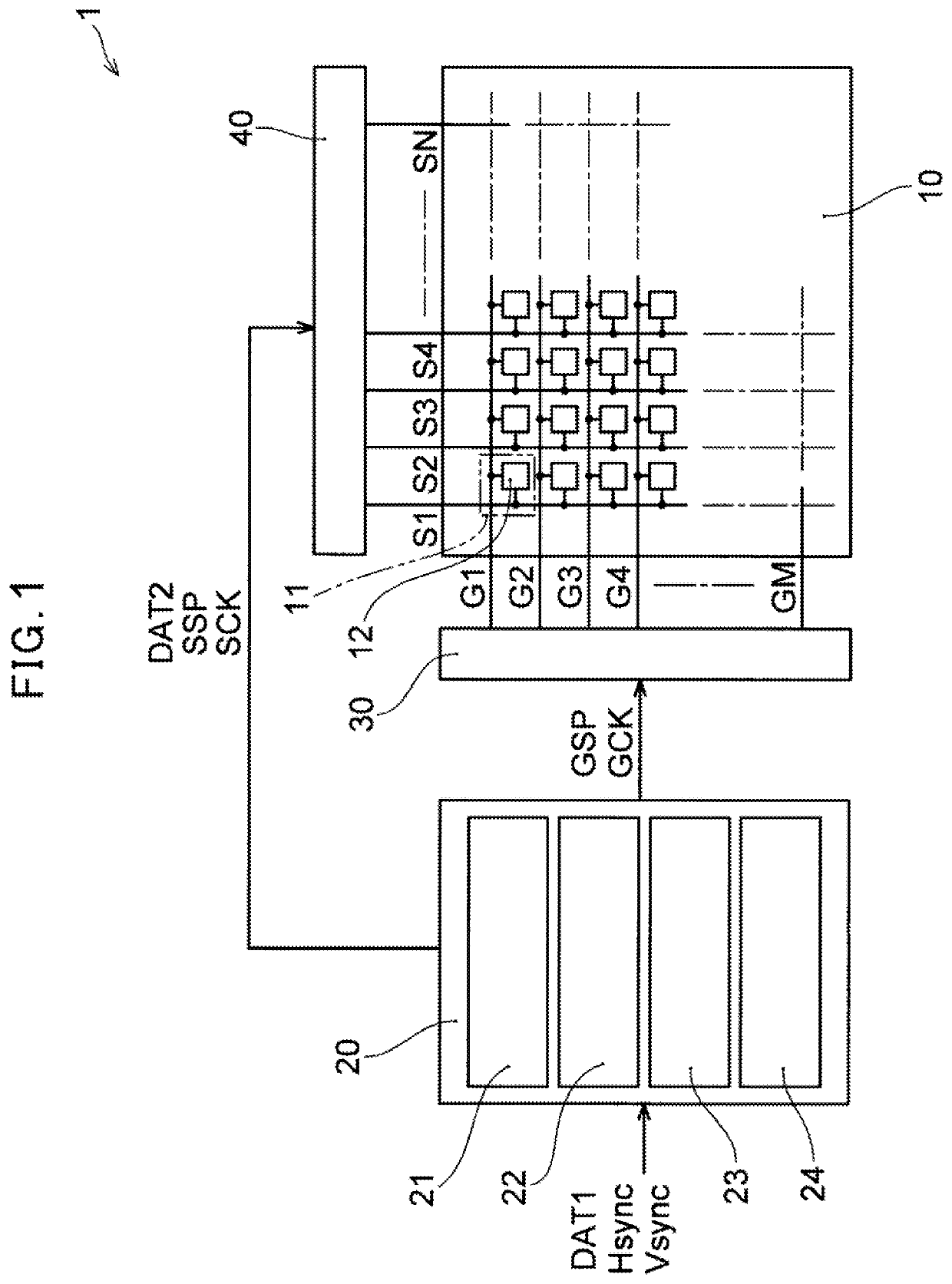
[0023]FIG. 1 shows a schematic block diagram of a display apparatus 1 according to Embodiment 1. The display apparatus 1 according to the present Embodiment comprises a display panel 10, a timing control unit 20, a scanning line drive unit 30, and a data line drive unit 40.

[0024]The display panel 10, comprising, for example, an active matrix-type liquid crystal display panel, or the like, comprises a plurality of pixels 11 arranged in a matrix, the plurality of pixels 11 being arranged in a display area. The display panel 10 comprises scanning lines G1 to G4, . . . , GM connected to a group of pixels arranged in a row direction of the plurality of pixels 11, data lines S1 to S4, . . . , SN connected to a group pf pixels arranged in a column direction of the plurality...


PUM


Abstract

A display apparatus is disclosed. The display apparatus according to one Embodiment comprises: a plurality of pixels arranged in a matrix; a plurality of scanning lines; a plurality of data lines; a scanning line drive unit to generate a scanning signal for selecting a group of pixels arranged in the row direction based on a scanning clock signal and successively output the generated scanning signal to the plurality of scanning lines; a data line drive unit to output, to a plurality of data lines, data signals for supplying voltages to the group of pixels arranged in the row direction; and a timing control unit to control the drive timing of the scanning line drive unit and the data line drive unit based on a first clock signal, and to generate the scanning clock signal based on the first clock signal.

Description

CROSS-REFERENCE TO RELATED APPLICATIONS[0001]This application claims priority to and the benefit of priority of U.S. Provisional Application No. 62 / 772,270, filed on Nov. 28, 2018, the entire contents of which are incorporated herein by reference.BACKGROUNDTechnical Field[0002]The present disclosure relates to a display apparatus and a method for controlling a display apparatus.Description of Related Art[0003]In a display apparatus comprising a liquid crystal display panel in which are arranged, in a matrix, a plurality of data lines on which data signals are transmitted and a plurality of scanning lines on which scanning signals are transmitted, a timing signal for controlling video to be displayed on the display apparatus is generated, for example, by a timing generation device comprising a counter circuit. In such a timing generation device, there is a problem that, in a case the frequency of a clock signal input to the counter circuit is high, the number of bits required for the...

Claims


Application Information

Patent Timeline
Patent Type & Authority Patents(United States)
IPC IPC(8): G09G3/36G06F1/324
CPCG09G3/3677G09G3/3696G09G3/3688G09G2310/08G06F1/324G09G2320/0223G09G3/3648G09G3/2096G09G3/3611G09G5/008G09G5/18G09G2320/0233
Inventor SAWAHATA, JUNICHI
Owner SAKAI DISPLAY PROD
Why Eureka
Try Eureka