Surface light source device and liquid crystal display device

a liquid crystal display and light source technology, applied in the direction of optics, instruments, optical light guides, etc., can solve the problems of reduced light transmitted through the color filter, reduced luminance, and extremely reduced quantity of transmitted light, and achieve wide color reproduction range and high quality

Active Publication Date: 2017-07-11
MITSUBISHI ELECTRIC CORP
View PDF8 Cites 0 Cited by
  • Summary
  • Abstract
  • Description
  • Claims
  • Application Information

AI Technical Summary

Benefits of technology

[0012]It is an object of the present invention to provide a surface light source device and a liquid crystal display device which can display an image of high quality which is inexpensive and has a wide color reproduction range when simultaneously using at least two types of LED light sources or more as a light source of a surface light source device.
[0013]The surface light source device according to the present invention includes a plurality of light sources for emitting a plurality of light having different colors, and a light guide body for mixing the colors of the plurality of light and emitting light having colors mixed. The light guide body includes a light incident portion for causing the plurality of light to be individually incident, and a light emitting portion provided, beside the light incident portion and for changing propagation angles of the plurality of light which is incident from the light incident portion and propagated into the light guide body to mix colors, thereby controlling a quantity of light emission from the light guide body and a light emitting position.
[0015]The light guide body includes a light incident portion for causing the plurality of light to be individually incident, and a light emitting portion provided beside the light incident portion and for changing propagation angles of the plurality of light which is incident from the light incident portion and propagated into the light guide body to mix colors, thereby controlling a quantity of light emission from the light guide body and a light emitting position. Therefore, the colors of the plurality of light from the plurality of light sources are mixed in the light guide body and the light can be thus guided without waste. Consequently, utilization efficiency of the light can be enhanced and an image of high quality having a wide color reproduction range can be displayed. Moreover, it is possible to obtain the advantage without requiring a large number of light sources. Therefore, the surface light source device and the liquid crystal display device can be implemented at low cost.

Problems solved by technology

For this reason, if the color purity of the display color is to be increased, there is a problem in that a quantity of light transmitted through the color filter is decreased, resulting in reduction in a luminance.
If the color purity is to be increased in a wavelength region of 630 to 640 nm which is preferable as pure red in the red color, therefore, there is a problem in that the quantity of transmitted light is extremely reduced, resulting in significant reduction in a luminance.
For this reason, a large number of LED light sources are required so that a manufacturing cost is increased.
However, in order to cause the LED light sources to mix respective colors of light emitted therefrom so as to form a uniform white light, it is necessary to take the number and arrangement of the LED light sources into consideration, which is not easy.

Method used


Image

  • Surface light source device and liquid crystal display device
  • Surface light source device and liquid crystal display device
  • Surface light source device and liquid crystal display device

Examples


first preferred embodiment

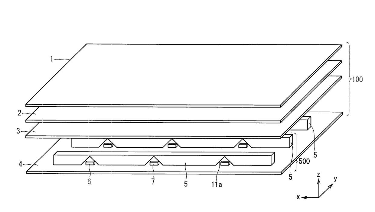
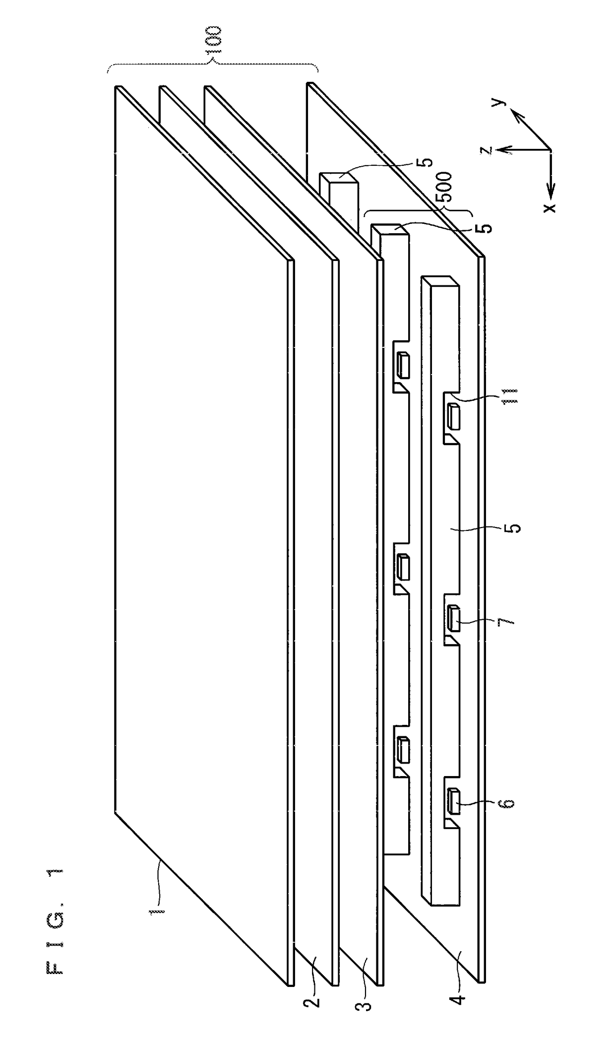
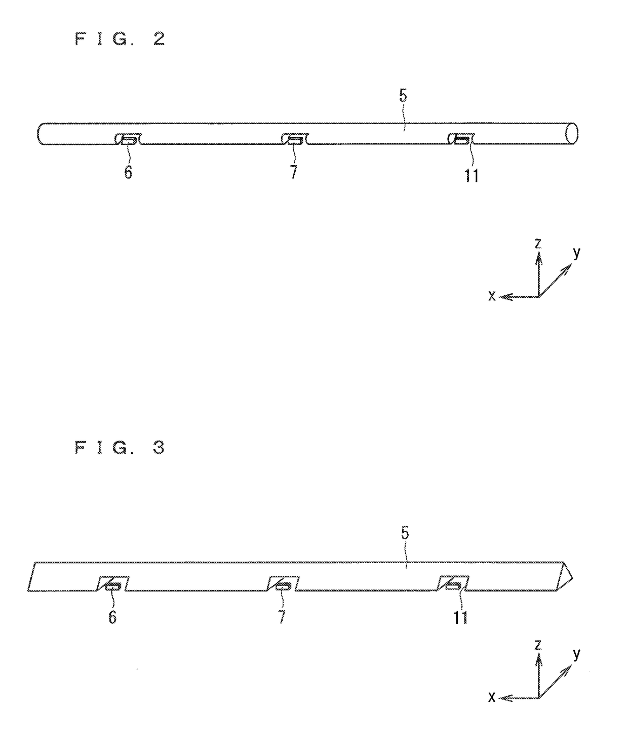
[0029]A first preferred embodiment according to the present invention will be described below with reference to the drawings. FIG. 1 is a perspective view schematically showing a structure according to an example of a liquid crystal display device 100 in accordance with a first preferred embodiment, FIG. 2 is a perspective view schematically showing a structure according to another example of a light guide body 5, FIG. 3 is a perspective view schematically showing a structure according to a still another example of the light guide body 5, FIG. 4 is a configuration view schematically showing a structure of the light guide body 5 of a surface light source device 500, FIG. 5A is a perspective view showing the structure of the light guide body 5, FIG. 5B is a perspective view showing a structure of a light emitting portion 8, and FIG. 6 is a configuration view schematically showing a function of the light emitting portion 8.

[0030]As shown in FIG. 1, the liquid crystal display device 100...

second preferred embodiment

[0046]Next, a liquid crystal display device 100 and a surface light source 500 according to a second preferred embodiment will be described. FIG. 7 is a perspective view schematically showing a structure according to an example of the liquid crystal display device 100 in accordance with the second preferred embodiment, and FIG. 8 is a configuration view schematically showing a function of a light incident portion 11a. In the second preferred embodiment, the same components as those described in the first preferred embodiment have the same reference numeral and explanation thereof will be omitted.

[0047]As shown in FIG. 7, in the second preferred embodiment, the light guide body 5 includes the light incident portion 11a obtained by deforming the recessed light incident portion 11 in place of the recessed light incident portion 11 in the structure according to the first preferred embodiment.

[0048]In order to reduce color irregularity in the surface light source device 500, it is prefer...

third preferred embodiment

[0054]Next, a liquid crystal display device 100 and a surface light source device 500 according to a third preferred embodiment will be described. FIG. 9 is a perspective view schematically showing a structure according to an example of the liquid crystal display device 100 in accordance with the third preferred embodiment and FIG. 10 is a configuration view schematically showing functions of a light incident portion 11 and a recessed structure portion 12. In the third preferred embodiment, the same components as those described in the first and second preferred embodiments have the same reference numerals and explanation thereof will be omitted.

[0055]As shown in FIG. 9, in the third preferred embodiment, a light guide body 5 includes a recessed structure portion 12 in the structure according to the first preferred embodiment. The recessed structure portion 12 is provided in a corresponding position to the light incident portion 11 on an upper surface 5b of the light guide body 5, a...


PUM

PropertyMeasurementUnit
red wavelengthaaaaaaaaaa
wavelength regionaaaaaaaaaa
angle θbaaaaaaaaaa

Abstract

A surface light source device includes a plurality of LEDs for emitting a plurality of light having different colors, and a light guide body for mixing the colors of the plurality of light and emitting light having colors mixed. The light guide body includes a light incident portion for causing the plurality of light to be individually incident, and a light emitting portion provided beside the light incident portion and changing propagation angles of the plurality of light which is incident from the light incident portion and propagated into the light guide body to mix colors, thereby controlling a quantity of light emission from the light guide body and a light emitting position.

Description

BACKGROUND OF THE INVENTION[0001]Field of the Invention[0002]The present invention relates to a surface light source device for illuminating a back surface of a liquid crystal display element by at least two types of light sources having different characteristics, thereby displaying an image on the liquid crystal display element, and a liquid crystal display device including the surface light source device.[0003]Description of the Background Art[0004]A liquid crystal display element provided in a liquid crystal display device does not emit light by itself. For this reason, the liquid crystal display device includes a backlight device (a surface light source device) as a light source for illuminating the liquid crystal display element at a back surface side of the liquid crystal display element.[0005]Moreover, the liquid crystal display element includes a color filter and transmits, through a color filter, only light having a part of wavelengths in light emitted from a fluorescent la...

Claims


Application Information

Patent Timeline
Patent Type & Authority Patents(United States)
IPC IPC(8): G02F1/1335F21V8/00
CPCG02F1/133609G02B6/0001G02F1/133603G02F1/133602G02F1/133606G02F1/133607G02B6/0021G02B6/0068G02B6/0078
Inventor MAEDA, SAKIOKIMOTO, NAMINIIKURA, EIJISAWANAKA, TOMOHIKOKIDA, HIROSHI
Owner MITSUBISHI ELECTRIC CORP
Why Eureka
Try Eureka