Filtering panel and method of making the same

a filter panel and filter frame technology, applied in the field of water purification, can solve the problems of reducing the flow of water which is filtered, affecting the quality of water purification, so as to reduce the distortion effect by deflection, avoid fatigue stress, and be sufficiently strong and robust

Active Publication Date: 2020-12-08
EVOQUA WATER TECH LLC
View PDF129 Cites 2 Cited by
  • Summary
  • Abstract
  • Description
  • Claims
  • Application Information

AI Technical Summary

Benefits of technology

[0018]Another object of the present invention is to manufacture filtering panels using metal cloth and avoid the fatigue stress in the vicinity of the areas where the metal cloth is attached to the frame. Further a solution is needed to reduce the distortion effect by deflection occurring typically when hydraulic load is applied on metal cloths such as stainless steel.
[0019]It is also desirable that the filter frames of disc filters should be made lighter than stainless steel frames and at the same time stay sufficiently sturdy and robust to enable more tensioning than with filtering panels using conventional polyester filter cloth.
[0020]A further object is to provide a filter cloth frame, which has dimensions of the known filter panels with polyester cloth, having the advantage of being introducible and suited for replacement in existing filter frame supports of disk filters for filter panels with polyester cloth.
[0021]Another object of the present invention is to provide a filter cloth frame which can be manufactured at relative low costs. Yet another object is to provide to make the manufacturing process as, for instance, fastening the metal cloth to a filter frame easier and less costly. More particularly, when cutting the expensive filter cloths such as woven stainless steel cloths for the filtering panels, there is the drawback that large amount of expensive filter cloth are wasted, when using conventional tensioning techniques. Therefrom derives the purpose to avoid filter cloth waste, when making the filtering panel.
[0022]A still further object of the present invention is to provide a tool allowing reliable attachment of a filter cloth to the filter cloth frame and reproducible conditions with regard to tensile properties of the filter cloth.
[0039]The solutions in accordance with the present disclosure provide a filtering panel, disk filter and method for making the filtering panel to significantly increase the lifetime of filtering panels with metal clothing such as for example stainless steel. Another advantage that may be realized in the manufacturing method is that tensioning can be provided while minimizing waste of the filtering cloth. No one advantage is critical to the embodiments.

Problems solved by technology

The size of the wires, as reduced, generates a net whose free area takes up between 10 and 15% of the surface of the cloth, with a consequent limitation of the flow of water which is filtered.
In particular it has been found that when they are stretched and fixed to the frame and used in a disk filter, in which they are subjected to a perpendicular hydraulic load which is reversed during the periodic phases of so-called backwashing, they are affected by the resulting phenomenon of fatigue, which leads them to premature breakage.
In said area of weakness there is a tendency to be torn away from the filter frame if the disk filter is in operation.
Said windows may be manufactured from stainless steel sheets by pressing through a die with the appropriate hole size pattern and have the disadvantage to reduce the effective filterimg area.
The solution described above results in a filter panel of a rather complex structure, in addition to involving the need for the frame also to be made of stainless steel, and also requiring a particular welding process of the filter cloth to the peripheral portion of the frame, which makes costs rise considerably.
All this, added to the higher cost of the stainless steel filter cloth compared to that of the polyester cloth, defeats the economic advantage of the optimisation of the features of permeability and facility of cleaning which are obtained by using the stainless steel filter cloth.

Method used


Image

  • Filtering panel and method of making the same
  • Filtering panel and method of making the same
  • Filtering panel and method of making the same

Examples


Embodiment Construction

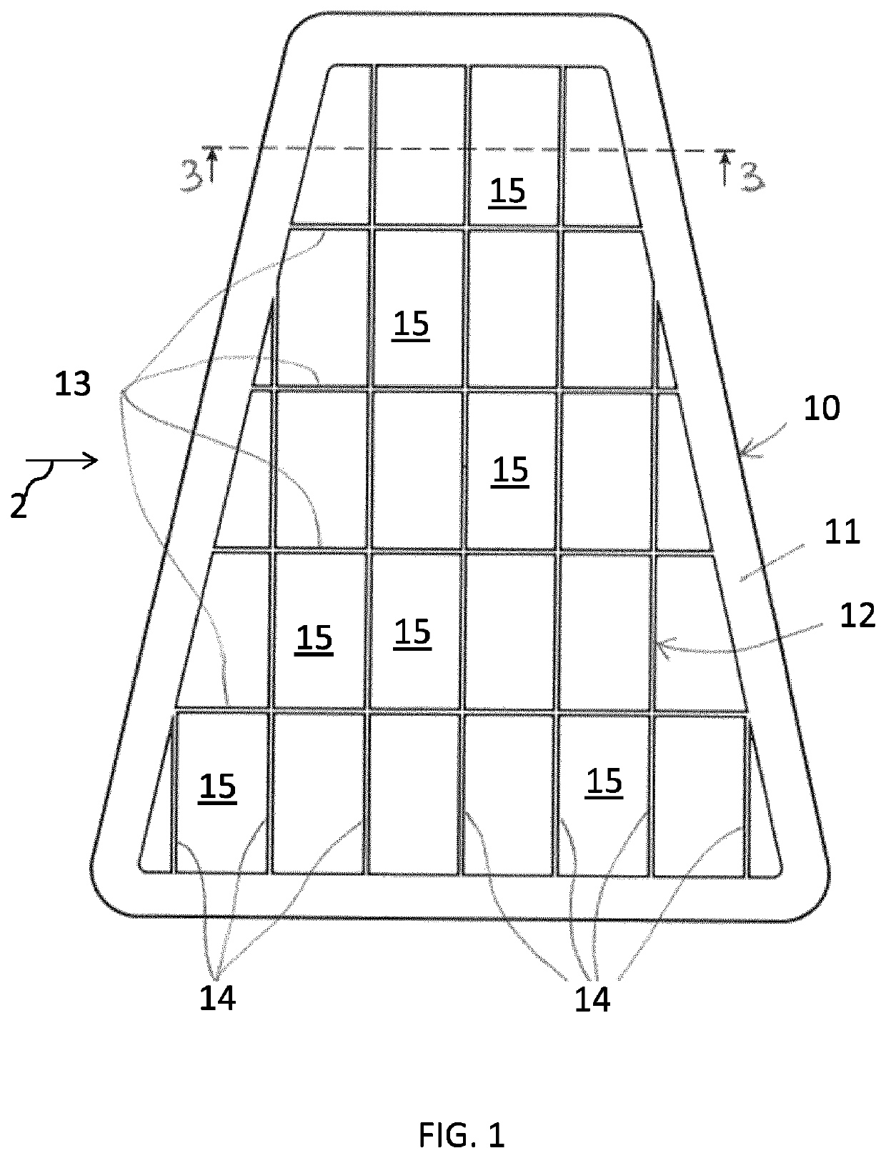
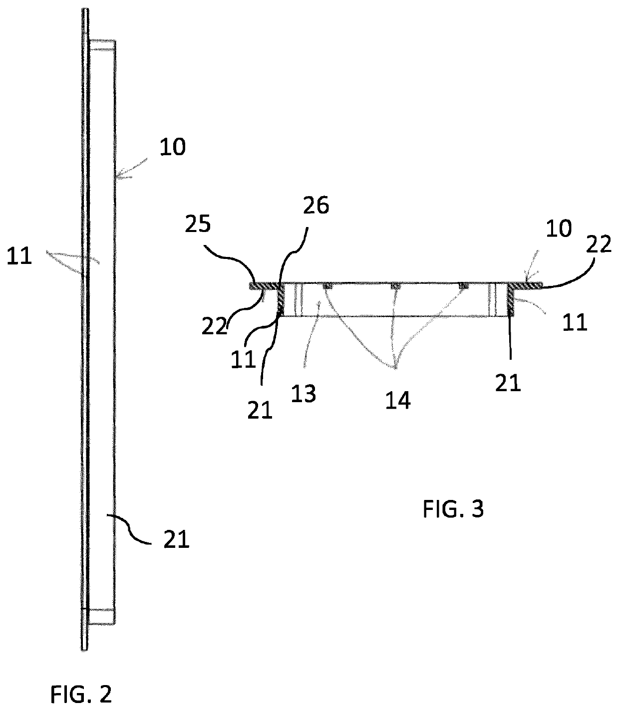
[0055]As can be seen from FIGS. 1-3, frame 10, in the trapezoidal form of the whole, comprises a peripheral frame 11 within which a grillwork is present, indicated as a whole with 12, formed of two series of perpendicularly intersecting strips, respectively 13 and 14, so as to form a multiplicity of fields 15 which, apart from some of the peripheral fields, are rectangular with the largest dimension which is a little less than twice that of the smallest. In this specific case the larger fields have an area which does not exceed 5% of the inner area to the peripheral portion 11. More generally, it is found that in order to be sure not to cause the fatigue phenomena illustrated above, the area of the field must not exceed 10% of the area inside the portion 11.

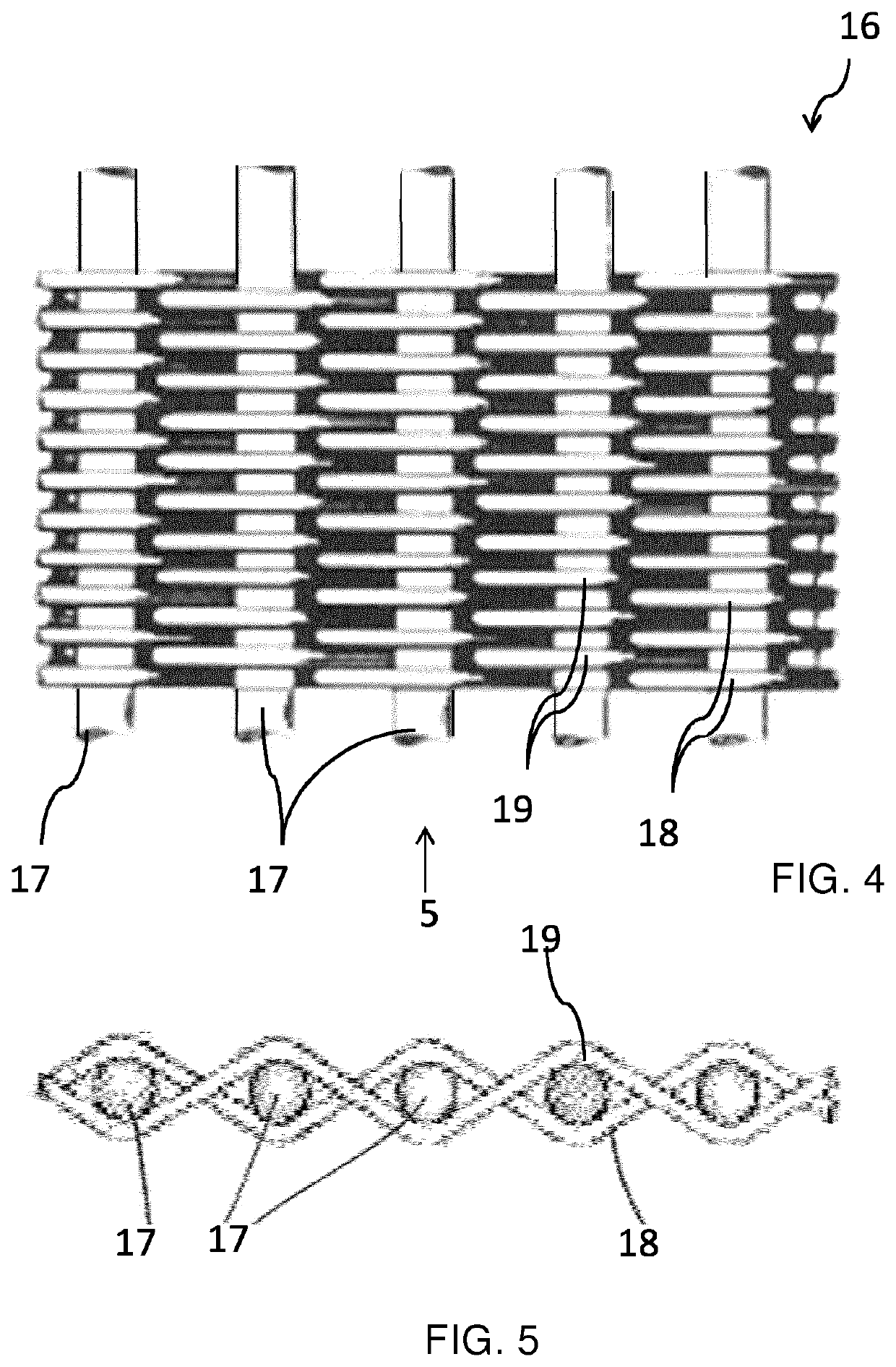
[0056]By using the grillwork constituting of the strips 13 and 14 in combination with the below prescribed pre-tensioning the deflection of the metal filter cloth 16, which is, for instance made of stainless steel, is significant...


PUM

PropertyMeasurementUnit
pore sizeaaaaaaaaaa
pore-sizeaaaaaaaaaa
distanceaaaaaaaaaa

Abstract

The present invention relates to a filtering panel (100) for a disk filter and a disk filter for water purification, comprising a metal filter cloth (16, 116) such as a stainless steel filter cloth, pre-tensioned in both warp and weft directions and fastened to a frame (10, 110) comprising a peripheral portion (11, 111), which is integral with an inner grillwork (12) and which divides the inner area of the peripheral portion (11, 111) into fields (15, 115). The frame (10, 110) comprises a plastic material reinforced with glass fibers or carbon fibres such as polypropylene loaded with fibreglass in an amount of at least 20 weight percent. Each field of the grillwork (12, 112) has an area not exceeding 10% of the inner area of the peripheral portion (11, 111). The pre-tensioning of the filter cloth (16, 116) in both directions is from at least 20% of the yield stress of the cloth (16, 116). Further the present invention relates to a disk filter comprising said filtering panels (100) and method of making said filtering panel (100).

Description

FIELD OF TECHNOLOGY[0001]The present invention relates to water purification and in particular a filtering panel used in filtration equipment called disk filter and a method of making the same. The filtration in a disk filter is obtained by means of a series of filter disks arranged coaxially and equidistantly.BACKGROUND[0002]Rotary disk filters comprising a drum having a central longitudinal axis and a plurality of filter disks or disk-shaped filter members being rotatably arranged about the axis are known from, for example, WO 2004 / 076026 A1 and WO2008 / 021270, the contents of which are hereby incorporated herein by reference in its entirety. During operation the longitudinal axis carrying the filter disks is rotated. From the interior of the drum a filtering liquid is conducted through openings into the disk filters.[0003]Each filter disk is composed of a series of equal filter panels, substantially trapezoid-shaped and arranged radially. Each filter panel comprises a peripheral f...

Claims


Application Information

Patent Timeline
Patent Type & Authority Patents(United States)
IPC IPC(8): B01D33/23B01D33/21B01D29/01B01D33/067B01D33/11B01D29/41B01D29/07B01D33/50B07B1/46
CPCB01D29/413B01D33/11B01D33/23B01D29/07B01D33/067B01D33/21B01D29/012B07B1/4618B01D33/50B01D2201/127
Inventor BRASCHI, MARCONEGRINI, ROBERTO
Owner EVOQUA WATER TECH LLC
Why Eureka
Try Eureka