
Fixing device for centering and distance adjusting of steel fiber tensioning and clamping clamp and testing method

A technology of clamping fixtures and fixing devices, applied in measuring devices, using stable tension/pressure testing materials, instruments, etc., can solve the problem of not real steel fiber tensile strength, reduce the test success rate, and steel fiber fracture damage and other problems, to achieve the effect of improving convenience, facilitating the splitting of work, and reducing interference.

Pending Publication Date: 2021-12-07
ZHENGZHOU UNIV
View PDF1 Cites 0 Cited by
  • Summary
  • Abstract
  • Description
  • Claims
  • Application Information

AI Technical Summary

Problems solved by technology

In order to better cooperate with a steel fiber tension clamping fixture and steel fiber tensile performance testing system (CN 105486592 A) invented by the previous inventors, it can test the mechanical properties of steel fibers more quickly and efficiently, and avoid clamping steel fiber In the process of installing the steel fiber tensioning and clamping fixture, the tensioning and clamping fixture repeatedly pulls, compresses and twists the steel fiber, which makes the steel fiber bear fatigue stress, thus causing different degrees of damage to the steel fiber, so that the test value is not true. The tensile strength of the steel fiber may even cause the steel fiber to break and damage in advance, reducing the success rate of the test. It is necessary to develop a fixing device with a simple structure and easy operation, which is used to adjust the centering distance of the steel fiber tensioning and clamping fixture.

Method used


Image

  • Fixing device for centering and distance adjusting of steel fiber tensioning and clamping clamp and testing method
  • Fixing device for centering and distance adjusting of steel fiber tensioning and clamping clamp and testing method
  • Fixing device for centering and distance adjusting of steel fiber tensioning and clamping clamp and testing method

Examples


Embodiment Construction

[0054] The following will clearly and completely describe the exemplary schemes of the embodiments of the present invention with reference to the accompanying drawings of the specific embodiments of the present invention. Unless otherwise defined, the technical terms or scientific terms used in the present invention shall have the usual meanings understood by those skilled in the art.

[0055] In the description of the present invention, it should be understood that the expressions "first" and "second" are used to describe each element of the present invention, and do not represent any order, quantity or importance limitation, but are only used to describe One component is distinguished from another.

[0056] It should be noted that when an element is "connected", "coupled" or "connected" to another element, it may mean that it is directly connected, coupled or connected, but it should be understood that there may be Intermediate elements; that is, positional relationships cove...


PUM


Abstract

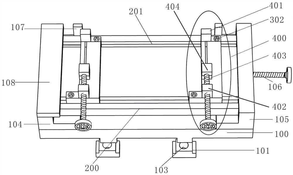
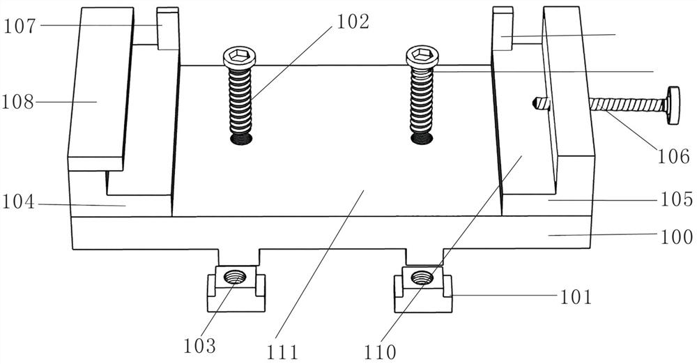
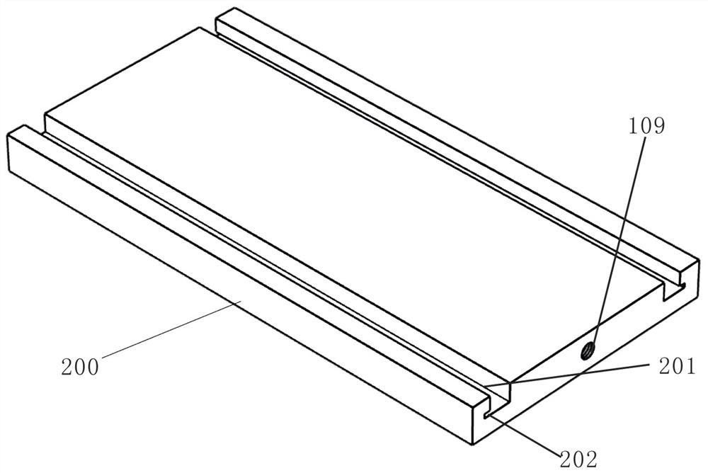
The invention belongs to the technical field of steel fiber mechanical property testing. Disclosed is a fixing device for centering and distance adjusting of a steel fiber tensioning and clamping clamp. The fixing device comprises a supporting table, a fixing unit, workbenches and clamping units. The fixing unit is used for fixing the supporting table to a foundation platform; the two workbenches are oppositely arranged on the supporting table left and right, a sliding locking unit is arranged on the supporting table, and the sliding locking unit is used for adjusting the distance between the two workbenches and fixing the workbenches and the supporting table; each workbench is correspondingly provided with one clamping unit, and the clamping units are used for fixing the steel fiber tensioning and clamping clamp. The invention further discloses a steel fiber tension testing method. The fixing device is reasonable in structural design, steel fibers can be effectively centered, positioned and clamped, non-directional tension, compression and torsion of the steel fibers in the clamping process are avoided, and the detection accuracy is improved.

Description

technical field [0001] The invention belongs to the technical field of steel fiber mechanical performance testing, and in particular relates to a fixing device and a testing method for centering distance adjustment of a steel fiber tensioning and clamping fixture. Background technique [0002] In order to accurately test the physical properties of steel fibers, especially the mechanical indicators such as tensile strength, elastic modulus and ultimate elongation, it is necessary to conduct direct tensile performance tests of steel fibers. In order to better cooperate with a steel fiber tension clamping fixture and steel fiber tensile performance testing system (CN 105486592 A) invented by the previous inventors, it can test the mechanical properties of steel fibers more quickly and efficiently, and avoid clamping steel fiber In the process of installing the steel fiber tensioning and clamping fixture, the tensioning and clamping fixture repeatedly pulls, compresses and twist...

Claims


Application Information

Patent Timeline
Patent Type & Authority Applications(China)
IPC IPC(8): G01N3/04G01N3/08
CPCG01N3/04G01N3/08G01N2203/0003G01N2203/0017G01N2203/04
Inventor 高丹盈张涛汤寄予庞育阳房栋杨林谷志强
Owner ZHENGZHOU UNIV
Learn More