
Laser 3D printer

a 3d printer and laser technology, applied in the direction of additive manufacturing processes, manufacturing tools, applying layer means, etc., can solve the problems of operating staff contamination, and achieve the effect of simple and economically advantageous production

Active Publication Date: 2020-12-15
3D4MEC SRL
View PDF5 Cites 0 Cited by
  • Summary
  • Abstract
  • Description
  • Claims
  • Application Information

AI Technical Summary

Benefits of technology

The aim of this patent is to create a laser 3D printer that is simpler and more cost-effective to produce than current models. The goal is to overcome the drawbacks and limitations of current technologies.

Problems solved by technology

Known laser 3D printers of the type described above present some drawbacks mainly resulting from the fact that the powdered material is fed by the dispenser directly and randomly onto the end plane before being distributed by the distributor over the lifting platform.
The configuration of the feeding unit hence entails a considerable dispersion of the powdered material in the surrounding environment, consequently with possible contamination of the operating staff.

Method used


Image

  • Laser 3D printer
  • Laser 3D printer
  • Laser 3D printer

Examples


Embodiment Construction

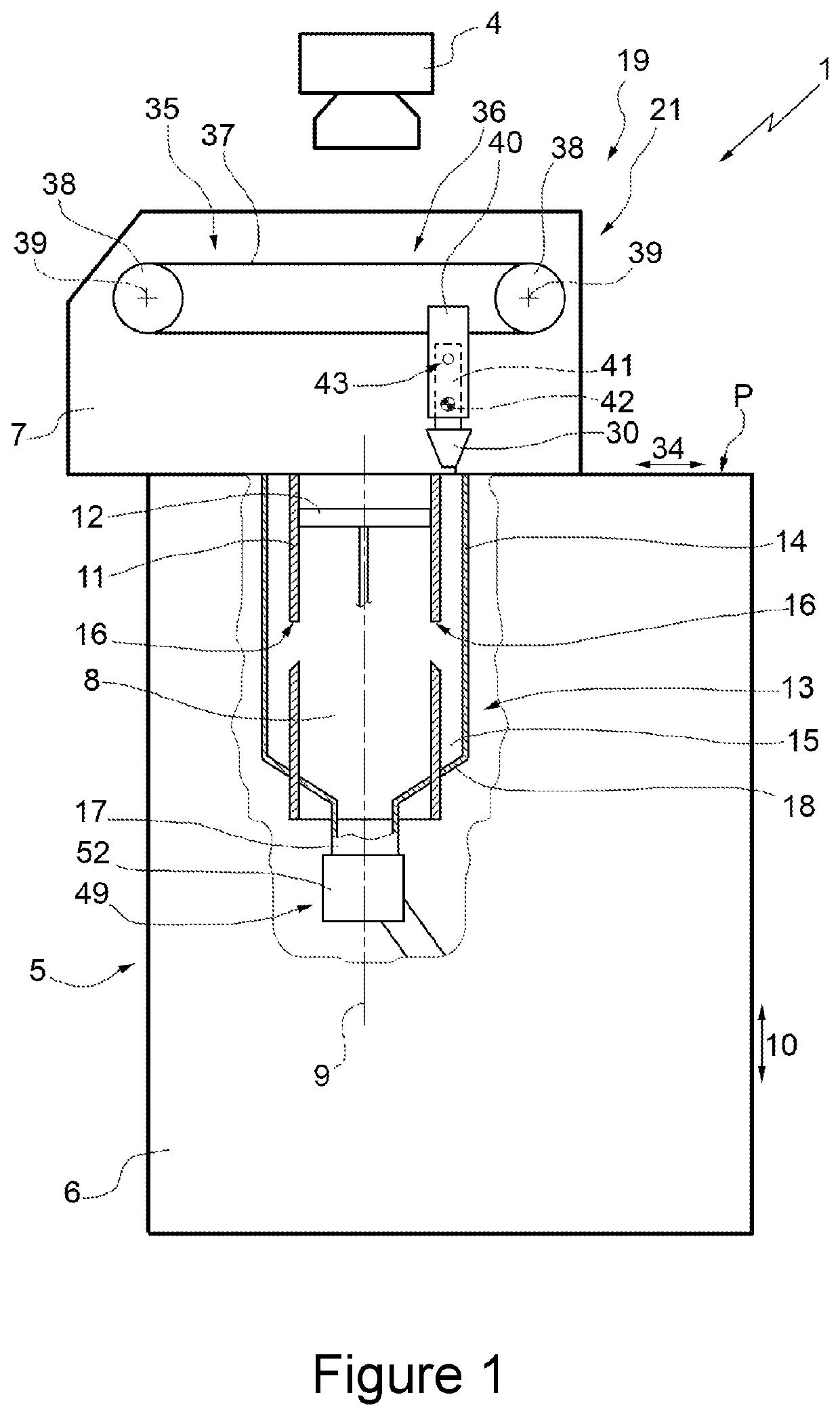
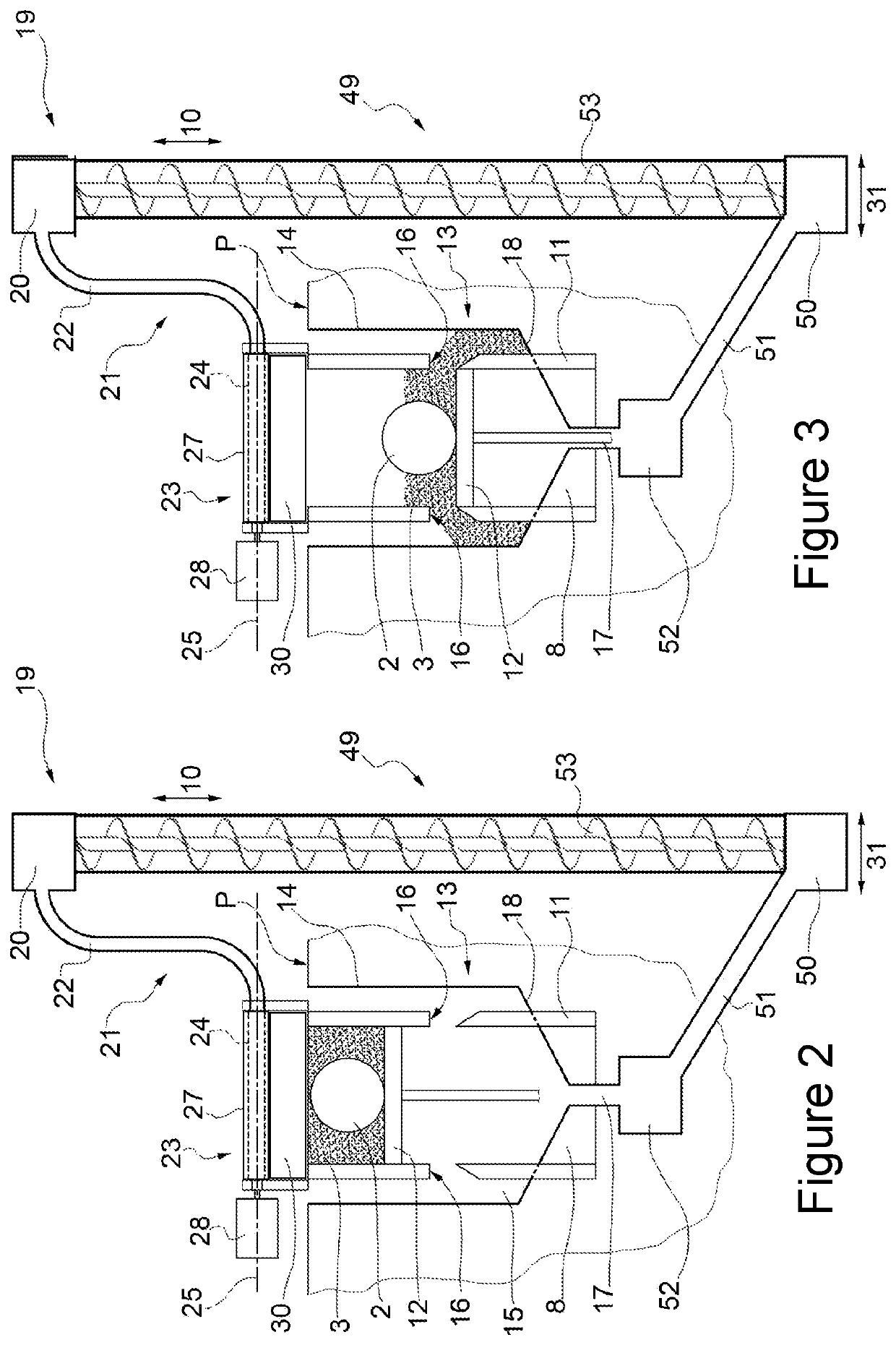
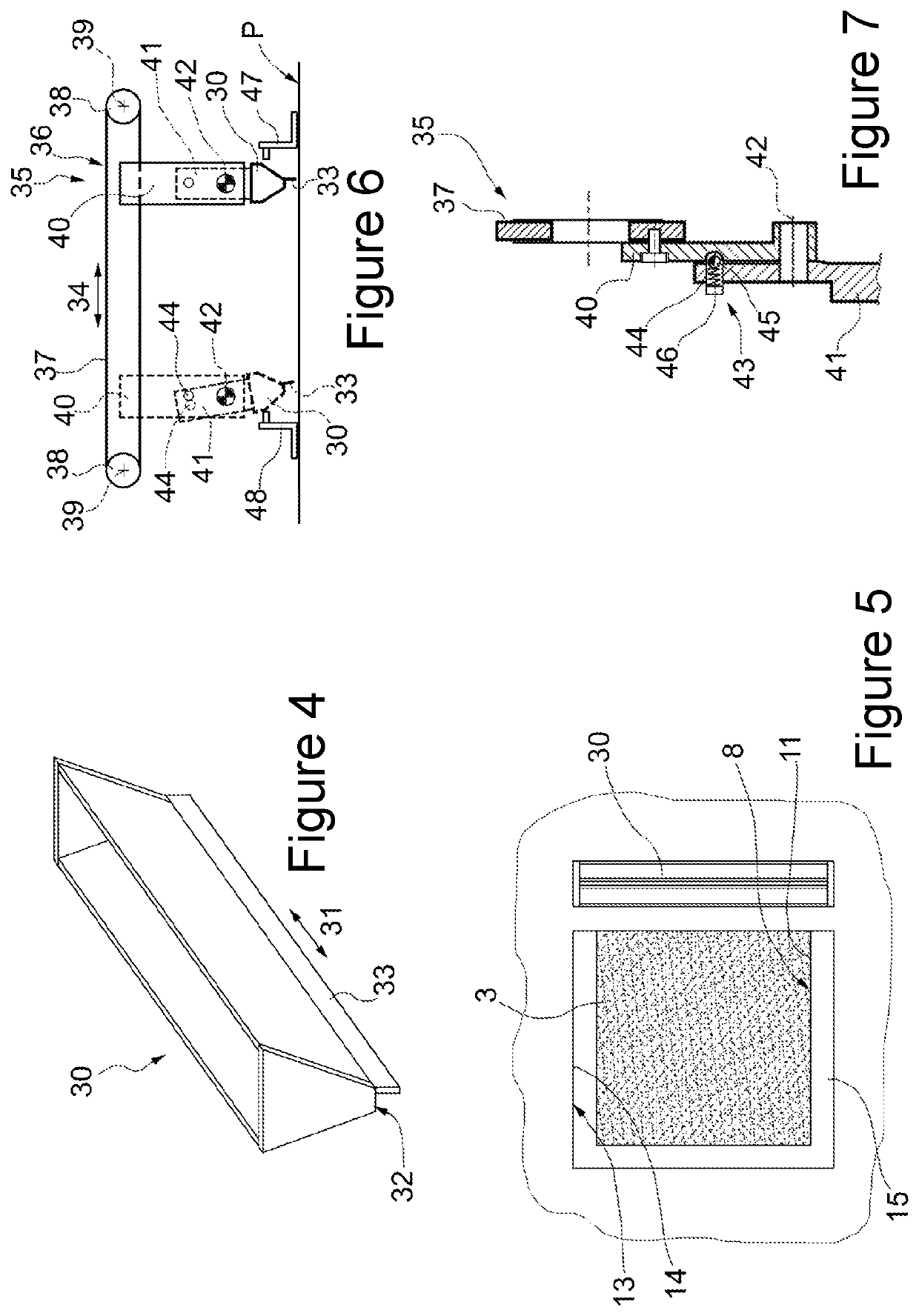
[0019]With reference to FIGS. 1, 2, and 3, designated as a whole by 1 is a laser 3D printer for producing three-dimensional objects 2 by sintering of a powdered material 3 using a laser head 4.

[0020]The printer 1 comprises a supporting frame 5, which in turn comprises a bottom box-shaped body 6 and a top box-shaped body 7 connected together along a substantially horizontal plane P of separation.

[0021]The body 6 houses within it a tubular compartment 8, which has a longitudinal axis 9 parallel to a substantially vertical direction 10 perpendicular to the plane P, extends downwards starting from the plane P, and has a cross section having a substantially square shape.

[0022]The compartment 8 is limited by a side wall 11 engaged in a sliding manner by a lifting platform 12, which extends perpendicular to the direction 10 and is mobile along the compartment 8 in the direction 10 itself under the thrust of a driving device (known and not illustrated).

[0023]The platform 12 is connected to ...


PUM

PropertyMeasurementUnit
angleaaaaaaaaaa
dispersionaaaaaaaaaa
shapeaaaaaaaaaa

Abstract

A laser 3D printer presents a tubular compartment; a lifting platform slidably engaged in the tubular compartment; a dispenser for feeding a given amount of powdered material onto the lifting platform; a distributor for distributing the powdered material over the lifting platform; and a laser printing head for sintering the powdered material laid on the lifting platform; the distributor having the shape of a hopper converging downwards and being configured for receiving the powdered material from the dispenser.

Description

CROSS-REFERENCE TO RELATED APPLICATIONS[0001]This application is related to Italian Patent Application No. 102016000068832 filed on Jul. 1, 2016, the disclosure of which is incorporated by reference.TECHNICAL FIELD[0002]The present invention relates to a laser 3D printer.[0003]In particular, the present invention relates to a laser 3D printer of the type comprising a substantially vertical tubular compartment, which extends downwards starting from an end plane; a lifting platform engaged in a sliding manner in the tubular compartment; a feeding unit for feeding a powdered material onto the lifting platform; and a laser printing head for sintering the powdered material laid on the lifting platform.[0004]The lifting platform is progressively lowered to enable the feeding unit to feed each time a new layer of powdered material onto the lifting platform at the end of each operating cycle of the laser printing head.BACKGROUND OF THE INVENTION[0005]Generally, the feeding unit comprises a ...

Claims


Application Information

Patent Timeline
Patent Type & Authority Patents(United States)
IPC IPC(8): B29C64/321B29C64/255B33Y30/00B33Y40/00B29C64/329B29C64/205B29C64/153B29C64/357B29C64/245
CPCB29C64/357B29C64/321B29C64/245B29C64/205B33Y30/00B33Y40/00B29C64/329B29C64/255B29C64/153
Inventor CORSINI, GIUSEPPECARLONI, GABRIELE
Owner 3D4MEC SRL
Learn More