
Heat exchanger

a technology of heat exchanger and heat exchanger plate, which is applied in the direction of central heating exchanger, water heater, lighting and heating apparatus, etc., can solve the problem that the test step can practically take place, and achieve the effect of high flexibility, simple and economically advantageous production, and efficient operation

Active Publication Date: 2015-11-24
COSMOGAS
View PDF20 Cites 0 Cited by
  • Summary
  • Abstract
  • Description
  • Claims
  • Application Information

AI Technical Summary

Benefits of technology

The present invention aims to provide a heat exchanger that is efficient, compact, and easy to produce and test. The invention is a type of heat exchanger called a condensation heat exchanger, which has certain features described in the attached claims. These features make the heat exchanger flexible for production and installation. The technical effects of the invention are improved heat exchanger operation and design that leads to compact dimensions and simple production and installation processes.

Problems solved by technology

These known solutions then present the further drawback that the testing step can practically take place only when the heat exchanger has been practically completely assembled, namely with the set of coiled conduits mounted within the casing.
In the case of production defects (for example, leakages of liquid owing to non-perfect welds or seals), the product must be at least in part dismantled, with the times and costs that this involves.

Method used


Image

  • Heat exchanger
  • Heat exchanger
  • Heat exchanger

Examples


Embodiment Construction

[0022]The reference to “an embodiment” or “one embodiment” in this description is intended to indicate that a particular configuration, structure, or characteristic described in relation to the embodiment is comprised in at least one embodiment. Hence, phrases such as “in an embodiment” or “in one embodiment” and the like that may be present in different points of this description do not necessarily all refer to one and the same embodiment. Furthermore, the particular configurations, structures, or characteristics can be combined in any adequate way in one or more embodiments. The references used herein are merely for convenience and do not define the sphere of protection or the scope of the embodiments.

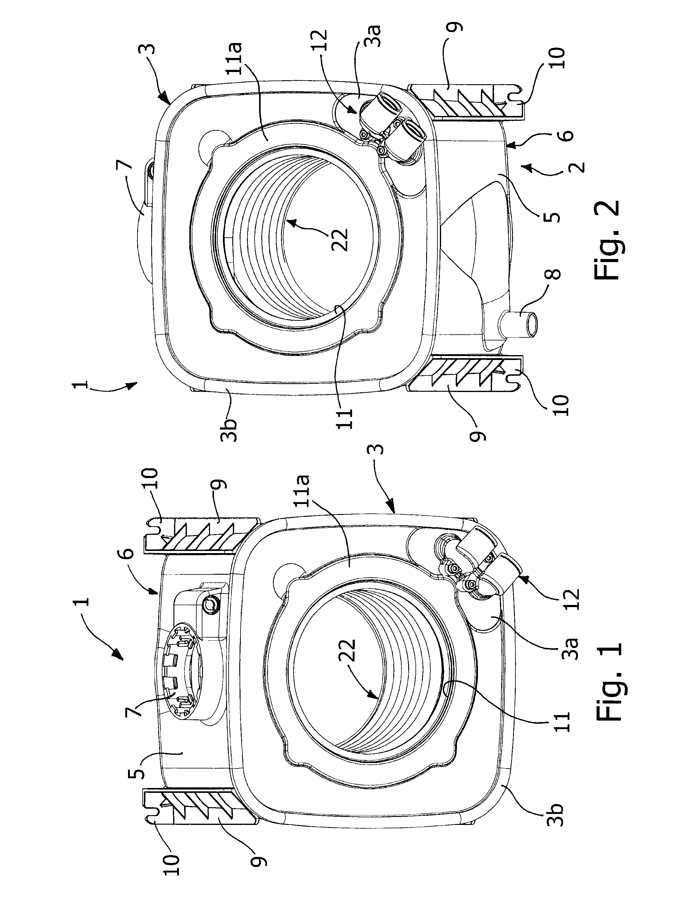
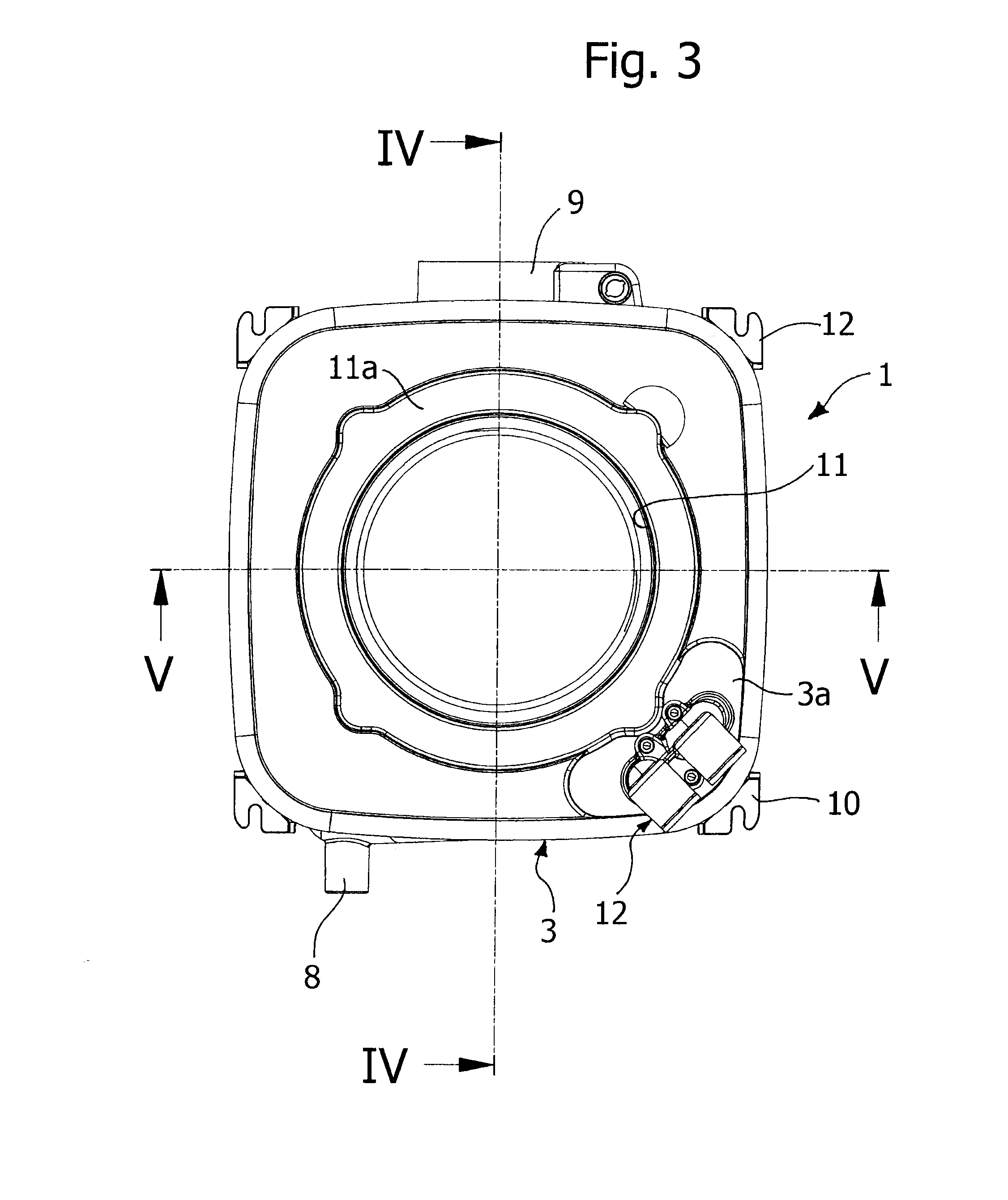
[0023]Designated as a whole by 1 in the figures is a heat exchanger, in particular of the condensation type, for a gas boiler built according to the present invention.

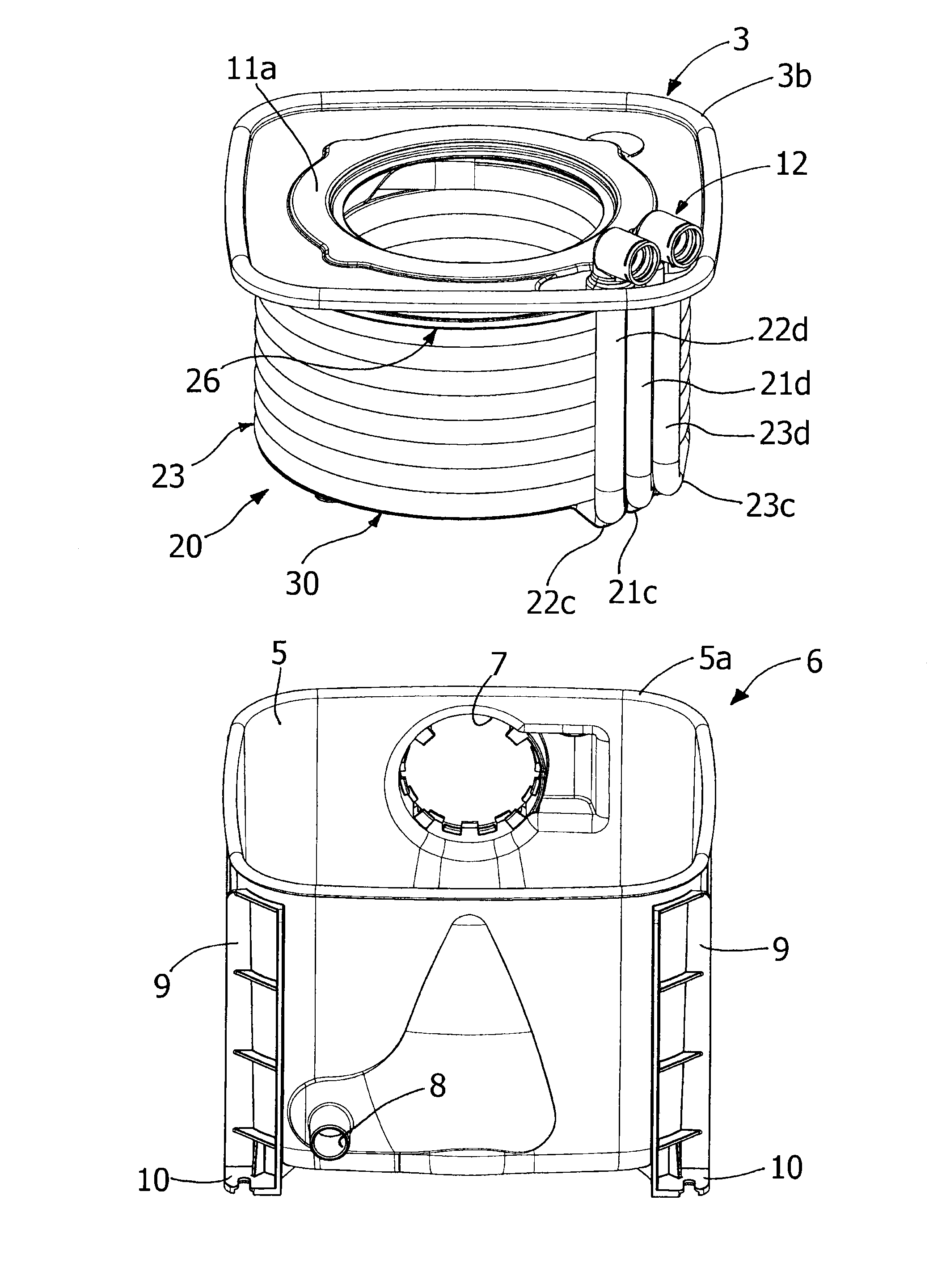
[0024]The heat exchanger 1 comprises a casing 2 having two end walls 3 and 4, herein defined as front and rear, and a...


PUM


Abstract

A heat exchanger has an exchanger unit, including at least one first coiled conduit and one second coiled conduit that are substantially coaxial, and a casing for housing the exchanger unit. The casing has a first end wall, a second end wall, and a peripheral part between the two end walls. Each conduit has an inlet and an outlet, where the outlet of the first conduit is connected substantially in series to the inlet of the second conduit. The exchanger unit is supported by the first end wall of the casing, with the inlet of the first conduit and the outlet of the second conduit which are substantially at the first end wall of the casing.

Description

CROSS REFERENCE TO RELATED APPLICATIONS[0001]This application is a national stage filing under section 371 of International Application No. PCT / IB2011 / 051169, filed on Mar. 21, 2011, and published in English on Sep. 29, 2011, as WO 2011 / 117802 and claims the priority of Italian application No. TO2010A000222 filed on Mar. 22, 2010, the entire disclosure of these applications being hereby incorporated herein by reference.FIELD OF THE INVENTION[0002]The present invention relates to a heat exchanger, in particular of the condensation type.PRIOR ART[0003]The function of a heat exchanger is that of transferring thermal energy between two fluids: for example, in the case of domestic gas boilers, the function of the heat exchanger is to heat water that circulates inside it, starting from the hot fumes that result from the combustion produced via a burner. Said boilers are conceived for exploiting both the heat that develops following upon combustion and the latent heat of condensation, cont...

Claims


Application Information

Patent Timeline
Patent Type & Authority Patents(United States)
IPC IPC(8): F24H1/43F24H9/14F28D7/02F24H9/02
CPCF24H9/02F24H1/43F24H9/142F24H9/146F24H9/148F24D2220/06Y02B30/00
Inventor ALESSANDRINI, ALBERTO
Owner COSMOGAS
Learn More