Airbag apparatus

a technology of airbags and airbags, which is applied in the direction of pedestrian/occupant safety arrangements, vehicular safety arrangements, vehicle components, etc., can solve the problems of difficult to suitably restrain each of the occupants, difficult to suitably ensure the restraint of the occupants, and difficult to suitably restrain the occupants in all directions. , to achieve the effect of reducing the cost and weight of an airbag apparatus, reducing the amount of airbags, and reducing the shap

Active Publication Date: 2020-12-15
HONDA MOTOR CO LTD
View PDF23 Cites 3 Cited by
  • Summary
  • Abstract
  • Description
  • Claims
  • Application Information

AI Technical Summary

Benefits of technology

[0011]Accordingly, an occupant can be suitably restrained by each of the bag bodies (particularly, the lower portion of each of the bag bodies) in all directions including forward in a vehicle body, outward in a vehicle width direction, and inward in the vehicle width direction with respect to the occupant. As a result, an occupant can be appropriately protected in all directions.
[0014]Accordingly, an occupant can be suitably restrained by each of the bag bodies (particularly, the lower portion of each of the bag bodies) in all directions including forward in the vehicle body, outward in the vehicle width direction, and inward in the vehicle width direction with respect to the occupant. As a result, an occupant can be appropriately protected in all directions.
[0018]As a result, an occupant can be suitably restrained by each of the bag bodies (particularly, the lower portion of each of the bag bodies) in all directions including forward in the vehicle body, outward in the vehicle width direction, and inward in the vehicle width direction with respect to the occupant.
[0022]Accordingly, an occupant can be suitably restrained by each of the bag bodies (particularly, the lower portion of each of the bag bodies) in all directions including forward in the vehicle body, outward in the vehicle width direction, and inward in the vehicle width direction with respect to the occupant. As a result, an occupant can be appropriately protected in all directions.
[0024]Here, the upper portion of the second flow channel is formed in the upper portion of the second bag body. In addition, the upper portion of the second flow channel is formed in a tapered shape. Thus, in a state in which the second flow channel is filled with gas, it is possible to minimize inflation of the upper portion of the second bag body in the width direction due to the inflated second flow channel. Accordingly, the upper portion of the second bag body can be inhibited from being contracted in the length direction.
[0028]In this manner, when the end portion of the gas flow channel formed in the third bag body has a closed structure, gas supplied from the inflator can be prevented from being discharged out of the airbag's bag body. Thus, the supplying amount of gas supplied from the inflator to the inside of the airbag's bag body can be minimized. Accordingly, the shape of the inflator is minimized, and reduction in costs and weight reduction in an airbag apparatus can be realized.

Problems solved by technology

Thus, it is difficult to suitably restrain each of occupants in the seat for a driver and the seat for a passenger inward in a vehicle width direction.
Therefore, it is difficult to suitably restrain occupants in all directions to a front side of a vehicle body, an outer side in the vehicle width direction, and an inner side in the vehicle width direction.
Therefore, it is difficult to suitably ensure restraining of occupants in the seat for a driver and the seat for a passenger outward in the vehicle width direction.

Method used


Image

  • Airbag apparatus
  • Airbag apparatus
  • Airbag apparatus

Examples


first embodiment

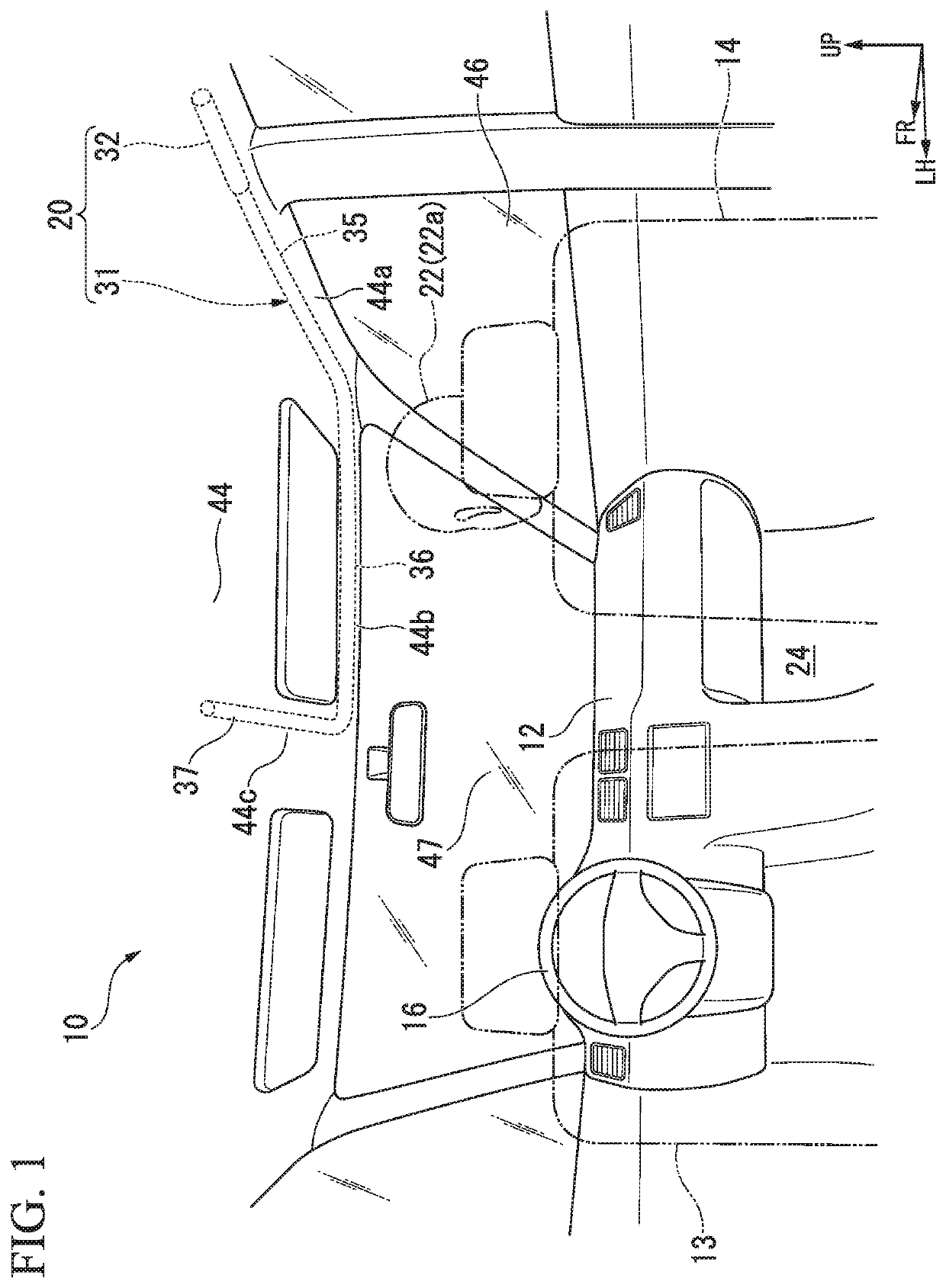
[0040]As illustrated in FIG. 1, the vehicle 10 includes an instrument panel 12, the driver's seat 13, the passenger seat 14, a steering wheel 16, and an airbag apparatus 20.

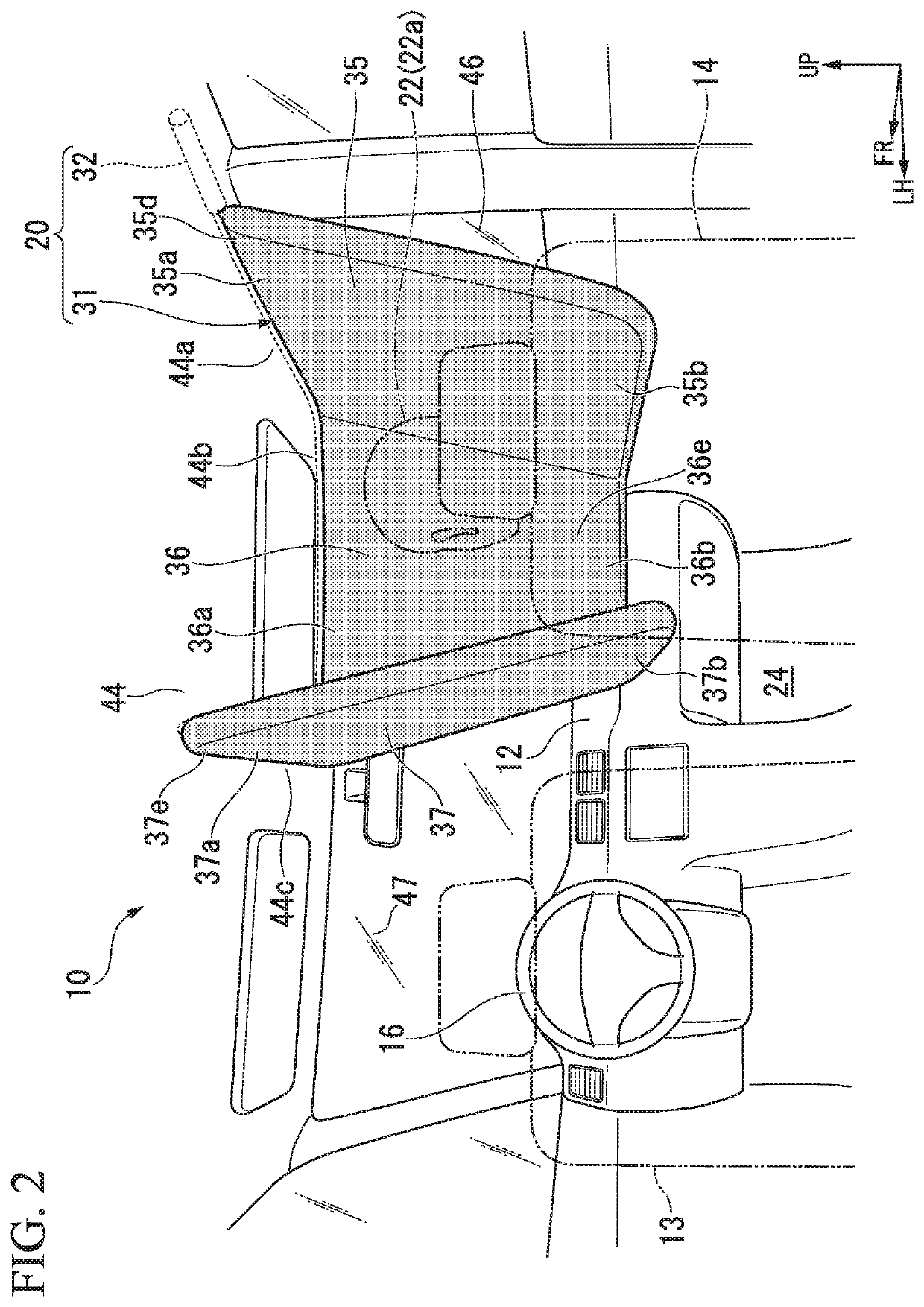
[0041]In the embodiment, the airbag apparatus 20 which restrains and protects an upper half 22a of the body of an occupant 22 sitting on the passenger seat 14 will be described as a representative example.

[0042]The instrument panel 12 is provided on the front side of a vehicle body in a vehicle interior 24. The driver's seat 13 and the passenger seat 14 are provided on the rear side of the vehicle body from the instrument panel 12. The steering wheel 16 is provided on the front side of the vehicle body from the driver's seat 13. A driver sits on the driver's seat 13. A passenger (who will hereinafter be referred to as an occupant) 22 sits on the passenger seat 14.

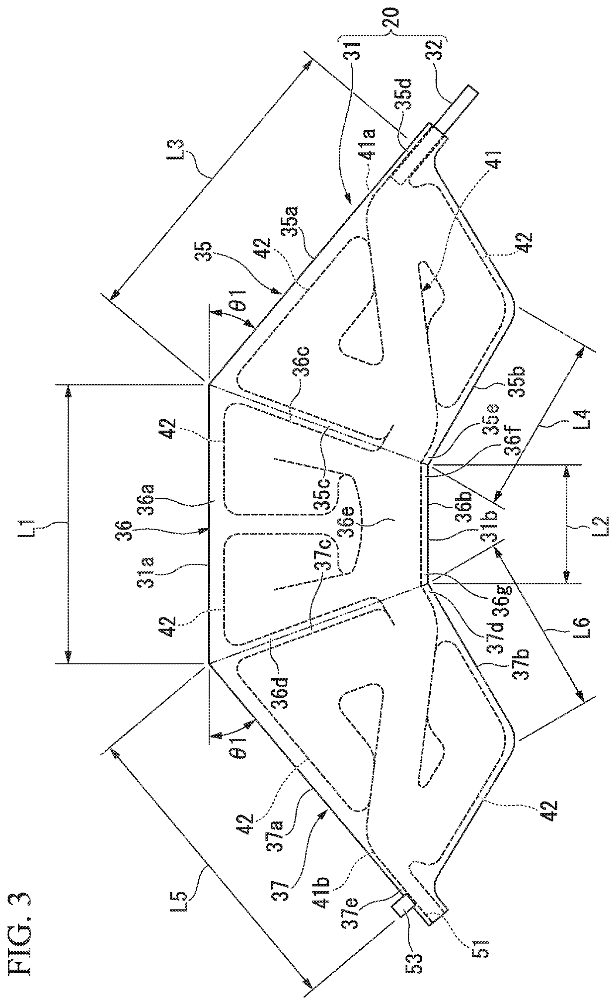
[0043]The airbag apparatus 20 includes an airbag's bag body 31 and an inflator 32.

[0044]The airbag's bag body 31 includes a first bag body 35, a second ...

second embodiment

[0092]As illustrated in FIG. 5, the airbag apparatus 70 includes an airbag's bag body 71 and the inflator 32. The airbag's bag body 71 includes a first bag body 74, a second bag body 75, a third bag body 76, a first flow channel 81 (refer to FIG. 6), and a plurality of second flow channels 82 (refer to FIG. 6).

[0093]Similar to the first to third bag bodies 35 to 37 of the first embodiment, the first bag body 74, the second bag body 75, and the third bag body 76 are folded in an accommodated state and are housed (mounted) above the head lining 44 of the vehicle 10.

[0094]Similar to the first to third bag bodies 35 to 37 of the first embodiment, the airbag's bag body 71 is formed in a U-shape in a state in which the first bag body 74, the second bag body 75, and the third bag body 76 are folded in an accommodated state.

[0095]In the airbag apparatus 70, when an impact load is input to the vehicle 10, gas is injected into the airbag's bag body 71 from the inflator 32, and the airbag's ba...

modification example

[0127]In the first embodiment and the second embodiment, examples, in which the opening portion 51 is formed in the trailing end portion (the end portion) 41b of the first flow channel 41 and the opening portion 85 is formed in the trailing end portion (the end portion) 81b of the first flow channel 81, have been described. However, the embodiments are not limited thereto. As an alternative example, for example, the opening portion 51 or the opening portion 85 may have a closed structure by stitching (suturing) the trailing end portions 41b and 81b to be blocked.

[0128]In this manner, if the trailing end portions 41b and 81b of the first flow channels 41 and 81 formed in the third bag bodies 37 and 76 have a closed structure, gas supplied from the inflator 32 can be prevented from being discharged out of the airbag's bag bodies 31 and 71. Thus, the supplying amount of gas supplied from the inflator 32 to the insides of the airbag's bag bodies 31 and 71 can be minimized.

[0129]Accordin...


PUM


Abstract

An airbag apparatus includes an airbag's bag body that inflates to be spread such that a front side and both sides of an occupant are surrounded. The airbag's bag body includes a first bag body, a second bag body, and a third bag body which are integrally formed. In a state in which the first bag body, the second bag body, and the third bag body have inflated to be spread, a lower portion of each of the bag bodies is disposed to be further attracted to the occupant side than an upper portion.

Description

CROSS-REFERENCE TO RELATED APPLICATION[0001]Priority is claimed on Japanese Patent Application No. 2017-254246, filed Dec. 28, 2017, the content of which is incorporated herein by reference.BACKGROUND OF THE INVENTIONField of the Invention[0002]The present invention relates to an airbag apparatus.Description of Related Art[0003]For example, airbag apparatuses, in which a front airbag inflates to be spread on a front side of a vehicle body with respect to occupants sitting on a seat for a driver and a seat for a passenger and side airbags inflate to be spread on outer sides in a vehicle width direction with respect to the occupants in the seats, are known. These airbag apparatuses are formed in a U-shape in a manner of covering occupants in the seat for a driver and the seat for a passenger with the front airbag and the side airbags on both sides.[0004]The front airbag inflates to be spread in an inclined shape on a downward gradient toward the occupant side from an upper end to a lo...

Claims


Application Information

Patent Timeline
Patent Type & Authority Patents(United States)
IPC IPC(8): B60R21/205B60R21/232B60R21/214B60R21/2334B60R21/233B60R21/213B60R21/231B60R21/16B60R21/00
CPCB60R21/2334B60R21/213B60R21/205B60R21/214B60R21/232B60R21/233B60R21/23138B60R2021/0048B60R2021/23308B60R2021/0004B60R2021/0006B60R2021/161B60R2021/23107B60R21/20
Inventor OBAYASHI, YUYAKOBATA, SEIJISATO, MASAHIRO
Owner HONDA MOTOR CO LTD
Why Eureka
Try Eureka