Low insertion loss high temperature stable fiber Bragg grating sensor and method for producing same

a fiber bragg grating, low insertion loss technology, applied in the direction of heat measurement, force measurement by measuring optical property variation, instruments, etc., can solve the problems of bragg gratings, affecting the quality of bragg gratings, and causing localized damage at the core-cladding interfa

Active Publication Date: 2020-12-15
NAT RES COUNCIL OF CANADA
View PDF36 Cites 0 Cited by
  • Summary
  • Abstract
  • Description
  • Claims
  • Application Information

AI Technical Summary

Problems solved by technology

A limitation of the prior-art UV-induced Type I fiber Bragg gratings, especially for high temperature sensor applications, is that operation of the sensor at elevated temperatures results in the removal or annealing of the UV-induced color centers and densification which are responsible for the induced index change of the grating.
The high intensity portions of the interference fringes created by two crossed UV beams split from a single UV beam create localized damage at the core-cladding interface within the fiber.
The drawback of this approach for induction of index change is that the Bragg gratings produced in this fashion have relatively low refractive index modulations (Δn=10−4) and are mechanically weak since the effective refractive index change results from periodic localized damage at the core-cladding interface.
When the pulse duration is long (>a few tens of picoseconds) laser-excited electrons can transfer energy to the surrounding lattice faster than the thermal diffusion of the material can remove the energy resulting in damage.
For damage grating structures written with long laser pulse durations greater than a few tens of picoseconds, the spectral quality of the resulting Bragg grating is often poor and there is often high scattering loss of the probe signal within the fiber.
As with the technique taught by Askins et al., the technique taught by Fokine also has the drawback that the induced index change of the Bragg gratings produced in this fashion have relatively low refractive index modulations (Δn=10−4).
The limitation in this approach to writing thermally stable gratings is that the grating structure erases at temperatures approaching 600° C. and it is limited to optical fibers possessing high internal stresses.
Although strong gratings can be formed using the approach taught in U.S. Pat. No. 6,993,221, the resulting Type II gratings suffer from high scattering loss making it difficult to concatenate a large number of Bragg grating sensors into a sensor array on a single length of optical fiber.
The threshold nature of the process also makes it more difficult to tailor the induced index profile of the grating in terms of its apodization, reflectivity and reflection bandwidth.
However, these gratings were not high temperature stable, and the index modulation, likely arising from color center formation and material densification, was erased at temperatures >800° C. These gratings were referred to as Type I fiber Bragg gratings.
Serious limitations to this approach exist because of the requirement for prolonged laser exposures which introduces wear and tear on the inscription laser as well as reduced reliability of the optical fiber.
The extra processing step of photosensitization can only be applied to Ge-doped fiber and is ineffective for other silica based optical fibers absent a Ge-dopant.

Method used


Image

  • Low insertion loss high temperature stable fiber Bragg grating sensor and method for producing same
  • Low insertion loss high temperature stable fiber Bragg grating sensor and method for producing same
  • Low insertion loss high temperature stable fiber Bragg grating sensor and method for producing same

Examples


example 1

Formation of Type II Bragg Grating with Low Insertion Loss

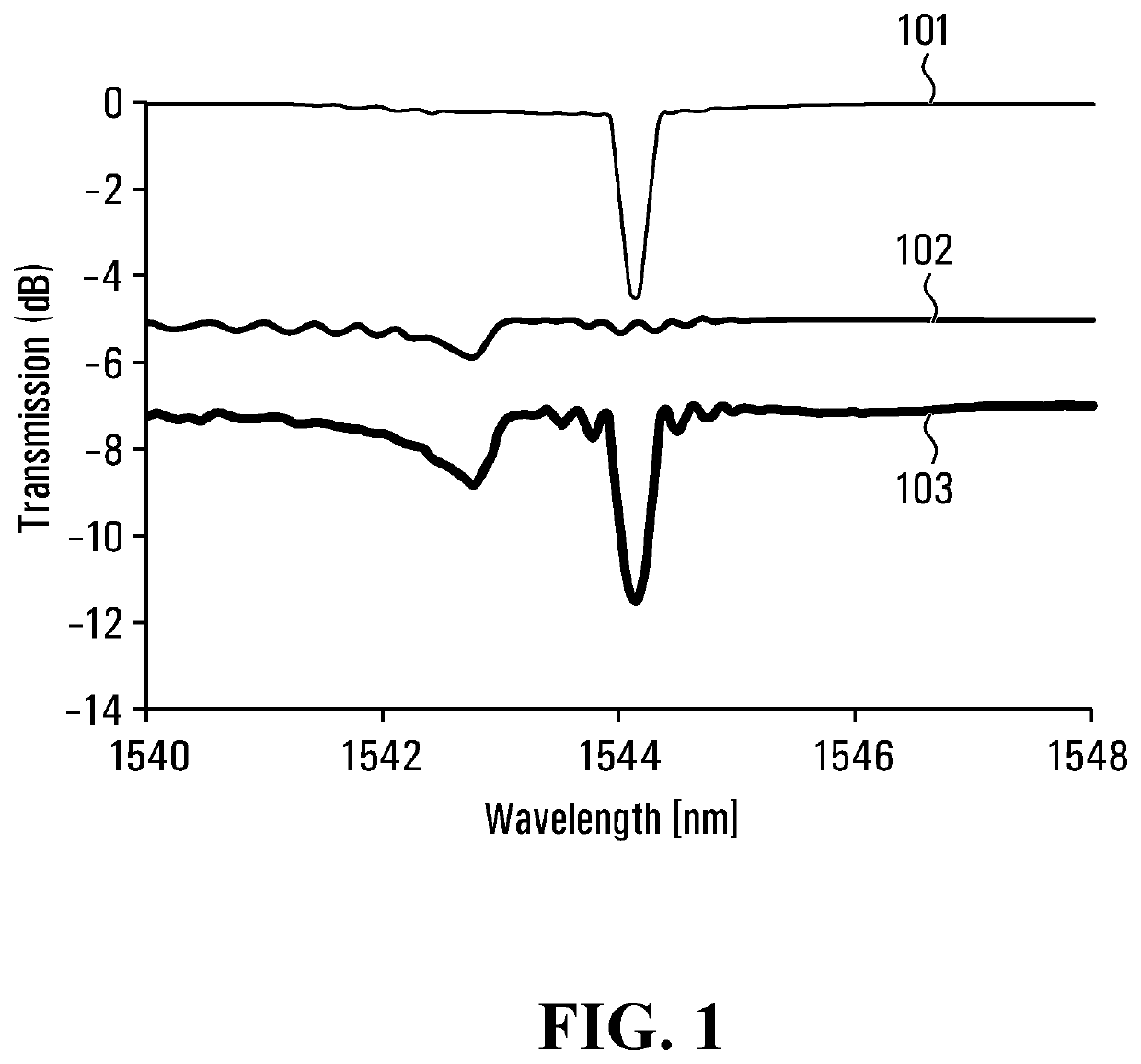
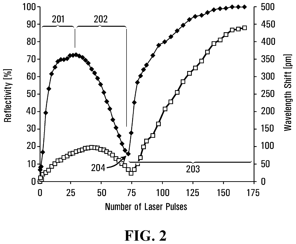
[0066]A regeneratively amplified Ti:sapphire femtosecond laser system with 80 fs pulse duration and operated at 800 nm wavelength was used as a laser source. The laser was operated at 5 Hz and 1 mJ laser pulse energy and the pulse chirped to 500 fs. The beam was focused through a 19 mm cylindrical lens and a phase mask with 1.065 μm pitch into the core of a standard Ge-doped core silica telecom fiber (Corning SMF-28; ˜4% Ge doping level core in a pure silica fiber substrate). The fiber was placed on a jig at 1 mm distance behind the phase mask ensuring pure two beam interference and a 532.5 nm grating pitch within the fiber. This periodicity in the fiber produced a fundamental Bragg resonance within the fiber. The laser beam was swept vertically across the fiber core at ˜3 μm / s by dithering the focusing lens. During the exposure, the evolution of the grating reflectivity was continuously monitored in both transmission and ref...

example 2

Thermal Treatment

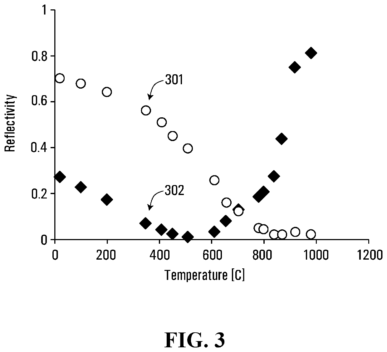
[0068]To test the effect of thermal treatment, two gratings were inscribed, side by side, on the same strand of fiber. First, a grating was written using the conditions detailed in Example 1, terminating the exposure when the grating was in the stage 202 of the grating structure evolution (i.e. irradiation terminated prior to Bragg resonance wavelength erasure). This grating is identified as (302) in FIG. 3. A second grating was written using grating inscription parameters needed to produce a Type I grating (laser pulse intensities below Ith). The second grating, whose annealing behavior is known, served as a reference to the annealing behavior of the first grating. The fiber was then inserted in the furnace and the temperature incremented by roughly 100° C. every hour. As shown in FIG. 3, the Type I grating (301) annealed as expected, losing half of its reflectivity around 500° C. and decreasing below the 2% reflectivity at 1000° C. The B grating (302) however, aft...

example 3

Fabrication of Grating Array with Irradiation Beyond Bragg Resonance Erasure

[0070]Applying the method described in Mihailov, S. J., Grobnic, D., Smelser, C. W., Lu, P., Walker, R. B. and Ding, H., “Bragg grating inscription in various optical fibers with femtosecond infrared lasers and a phase mask,” Opt. Mater. Express 1(4), 754-765 (2011), arrays were fabricated with up to 24 Type-II fs-IR FBGs, using phase masks having uniform periods between 1.043 μm and 1.097 μm. The gratings were written through a 19 mm focal-length cylindrical lens, using 800 nm, 350 fs, 0.85 mJ regeneratively amplified pulses, at a repetition rate of 3 Hz. The fiber surface was placed 200 μm from the phase mask and the beam was swept ±10 μm over its cross section with a frequency of 0.2 Hz. As a result of the phase mask to fiber proximity, the written grating periods are the same as the corresponding phase masks, resulting in second order Bragg resonances. The strip and recoat method was employed, and except...


PUM

PropertyMeasurementUnit
wavelengthaaaaaaaaaa
temperaturesaaaaaaaaaa
wavelength rangeaaaaaaaaaa

Abstract

Provided is an optical waveguide with an inscribed Bragg grating, where the Bragg grating is stable at high temperature, has low scattering loss and high reflectivity. Also provided is a method for inscribing a Bragg grating in an optical waveguide, the method comprising irradiating the optical waveguide with electromagnetic radiation from an ultrashort pulse duration laser of sufficient intensity to cause a permanent change in an index of refraction within a core of the optical waveguide, where the irradiating step is terminated prior to erasure of a Bragg resonance, and heating the optical waveguide to a temperature and for a duration sufficient to substantially remove a non-permanent grating formed in the optical waveguide by the irradiating step.

Description

FIELD OF THE INVENTION[0001]The present invention relates to methods for the formation of fiber Bragg gratings in optical waveguides and to sensing apparatus comprising such gratings. Such sensors can be used for measurement of pressure, strain, temperature, or displacement or index of refraction at a high temperature, for example up to 1000° C.BACKGROUND OF THE INVENTION[0002]Fiber Bragg grating (FBG) sensors are attractive devices for performing quasi-distributed temperature and strain measurements along an optical waveguide (e.g. optical fiber). Variations in the spectral response of the grating result from period changes in the Bragg grating due to strains or temperature variations that are experienced by the optical fiber when placed in a specific environment. These FBG sensors offer important advantages over other sensor technologies because of their electrically passive operation, electromagnetic interference (EMI) immunity, high sensitivity and multiplexing capabilities. Fib...

Claims


Application Information

Patent Timeline
Patent Type & Authority Patents(United States)
IPC IPC(8): G02B6/34G02B6/02G01L1/24G01D5/353G02B6/136G02B6/124
CPCG01K11/3206G02B6/02138G01D5/35316G01L1/246G02B6/34G02B6/124G02B6/136G02B6/02185
Inventor GROBNIC, DANMIHAILOV, STEPHENWALKER, ROBERTLU, PINGDING, HUIMINCOULAS, DAVIDHNATOVSKY, CYRIL
Owner NAT RES COUNCIL OF CANADA
Why Eureka
Try Eureka